An inductive strain sensor

A stress sensor and inductive technology, applied in the direction of instruments, measuring force, measuring devices, etc., can solve the problems of complex optical path processing equipment of sensors, no need for static pressure measurement, sensitive measurement temperature, etc., and achieve simple structure, easy maintenance and high sensitivity Effect

Active Publication Date: 2017-07-21
NINGBO INNOVATION CENT FOR APPLIED MAGNETICS CO LTD
View PDF6 Cites 0 Cited by
  • Summary
  • Abstract
  • Description
  • Claims
  • Application Information

AI Technical Summary

Problems solved by technology

However, the piezoelectric stress sensor is very sensitive to the measured temperature, and usually needs to be calibrated with an internal temperature measurement system or a constant temperature system; in addition, the piezoelectric stress sensor is mainly used for the measurement of acceleration and angular velocity, and is generally not used for static pressure measurement
The optical fiber strain sensor works on the principle that when the external stress changes, the light intensity, phase or polarization properties of the light propagating in the optical fiber change with the change of the external stress, but the sensor requires complex optical path processing equipment and is expensive

Method used


Image

  • An inductive strain sensor
  • An inductive strain sensor
  • An inductive strain sensor

Examples


Embodiment 1

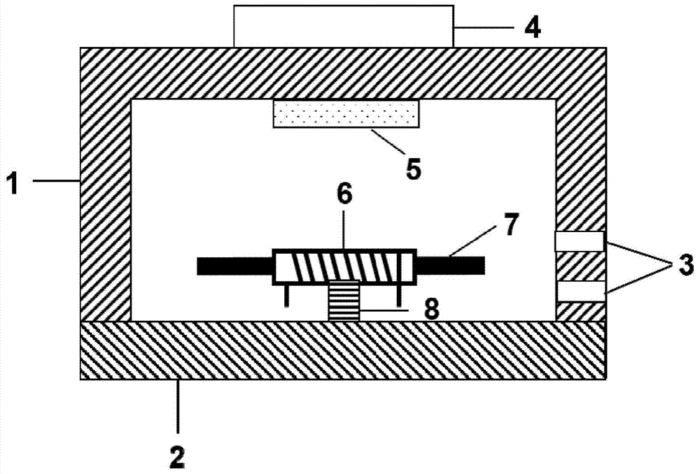
[0030] In this embodiment, the structure of the inductive stress sensor is as follows figure 1 As shown, it includes a supporting shell, a stress receiving body 4 connected to the outside of the supporting shell, and a magnet 5 and an inductance coil inside the supporting shell.

[0031] The supporting shell is composed of a base 2 and a shell 1 .

[0032] The inductance coil is composed of a magnetic core 7 and an air-core coil, and the magnetic core 7 passes through the inside of the air-core coil. The hollow coil is formed by winding the enameled wire around the periphery of the hollow cylinder 6 . The inductance coil is fixed on the base 2 through the fixing column 8, and the inductance coil is placed horizontally, that is, the length direction of the coil is parallel to the horizontal plane.

[0033] In the supporting shell, the part connected with the stress receiving body 4 is a pressure receiving part, the stress receiving body 4 is located on the outer wall surface ...

Embodiment 2

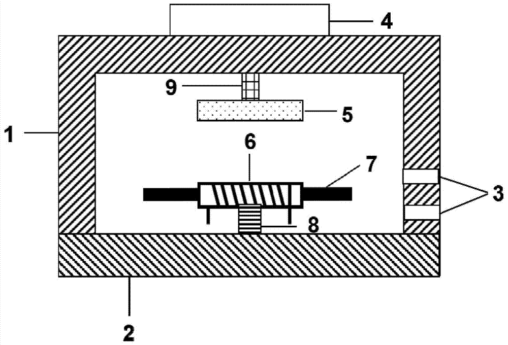
[0039] In this embodiment, the structure of the inductive stress sensor is as follows figure 2 As shown, the structure is basically the same as the structure of the inductive stress sensor in Embodiment 1, except that the magnet 5 is connected to the pressure-bearing part through the fixed column 9; the fixed column 9 is fixedly connected to the inner wall of the pressure-bearing part, and the magnet and the pressure-bearing part The fixed column 9 is fixedly connected, and the magnet is located directly below the position of the stress receiving body.

Embodiment 3

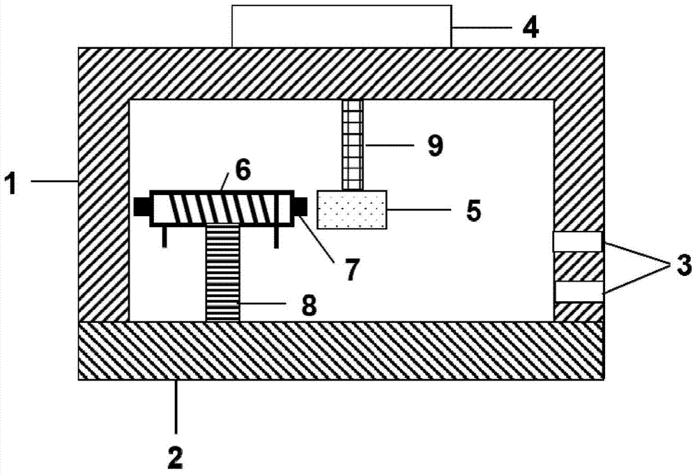
[0041] In this embodiment, the structure of the inductive stress sensor is as follows image 3 As shown, the structure is basically the same as that of the inductive stress sensor in Embodiment 2, except that the magnets 5 are distributed on the axis of the coil along the length direction.


PUM


Abstract

The invention provides an inductive stress sensor. The sensor includes a support shell, a stress-receiving body connected to the outside of the support shell, and a magnet and an inductance coil located inside the support shell; the magnet is connected with the inner wall of the pressure-bearing part; in the working state, the magnet provides the inductance coil Magnetic field, external stress acts on the stress-bearing body, and the pressure-bearing part is deformed by the compressive stress, causing the magnet to displace relative to the inductance coil, the magnetic field received by the inductance coil changes, and the coil impedance changes accordingly, and the impedance is output at both ends of the coil. The sensor has simple structure, high sensitivity and low cost, and can be used for high-stress monitoring such as expressway weight toll systems and industrial automatic weighing systems, and can also be used for micro-stress and strain monitoring.

Description

technical field [0001] The invention relates to the field of stress detection, in particular to an inductive stress sensor. Background technique [0002] The stress sensor is one of the commonly used sensors in the industry. It has important industrial application value and has been widely used in water conservancy and hydropower, railway transportation, intelligent buildings, production automation, aerospace, military, machine tools and many other industries. [0003] With the development of flexible electronics and wearable devices, stress sensors have attracted more and more attention. Traditional stress sensors are mainly mechanical structural devices, which use the elastic deformation of elastic elements or the pressure difference of the liquid column to feedback the applied pressure. The disadvantages are large size, heavy volume, and inability to provide power output, which is not conducive to system integration. With the development of science and technology, new ma...

Claims


Application Information

Patent Timeline
Patent Type & Authority Patents(China)
IPC IPC(8): G01L1/14
Inventor 李辉辉刘宜伟李润伟巫远招孙丹丹
Owner NINGBO INNOVATION CENT FOR APPLIED MAGNETICS CO LTD
Why Eureka
Try Eureka