
Laser hair removal instrument

A hair removal instrument and laser technology, applied in medical science, surgery, parts of surgical instruments, etc., can solve the problems of laser burnout, easy burnout, low photoelectric conversion rate of lasers, etc., to extend the service life, ensure photoelectric conversion efficiency, Guaranteed hair removal effect

Pending Publication Date: 2022-06-17
深圳市纬安共创生物科技有限公司
View PDF0 Cites 0 Cited by
  • Summary
  • Abstract
  • Description
  • Claims
  • Application Information

AI Technical Summary

Problems solved by technology

[0002] Traditional household laser hair removal instruments use side-emitting semiconductor lasers, and the light-emitting direction of the side-emitting semiconductor lasers is emitted parallel to the surface of the laser substrate. The photoelectric conversion rate of the laser is low, generally at 10%; and the operating temperature of the laser is 35°C and below, when the temperature exceeds 35°C, the photoelectric conversion rate of the laser will be lower, and it will be easier to burn out; some laser hair removal instruments use semiconductor cooling sheets to dissipate heat, but semiconductor cooling sheets are used to dissipate heat from the skin. To prevent the temperature of the skin from being too high when the laser is irradiated on the skin, the semiconductor cooling sheet is not used to dissipate heat for the laser. In this way, the temperature of the laser inside the hair removal device is still too high, and the working temperature of the laser will still be too high, resulting in Low photoelectric conversion rate, even laser burnout and other problems

Method used


Image

  • Laser hair removal instrument
  • Laser hair removal instrument
  • Laser hair removal instrument

Examples


Embodiment Construction

[0018] In order to make the purposes, technical solutions and advantages of the embodiments of the present application clearer, the technical solutions in the embodiments of the present application will be described clearly and completely below with reference to the drawings in the embodiments of the present application. Obviously, the described embodiments It is a part of the embodiments of this application, but not all of the embodiments. Based on the embodiments in the present application, all other embodiments obtained by those of ordinary skill in the art without creative work shall fall within the protection scope of the present application.

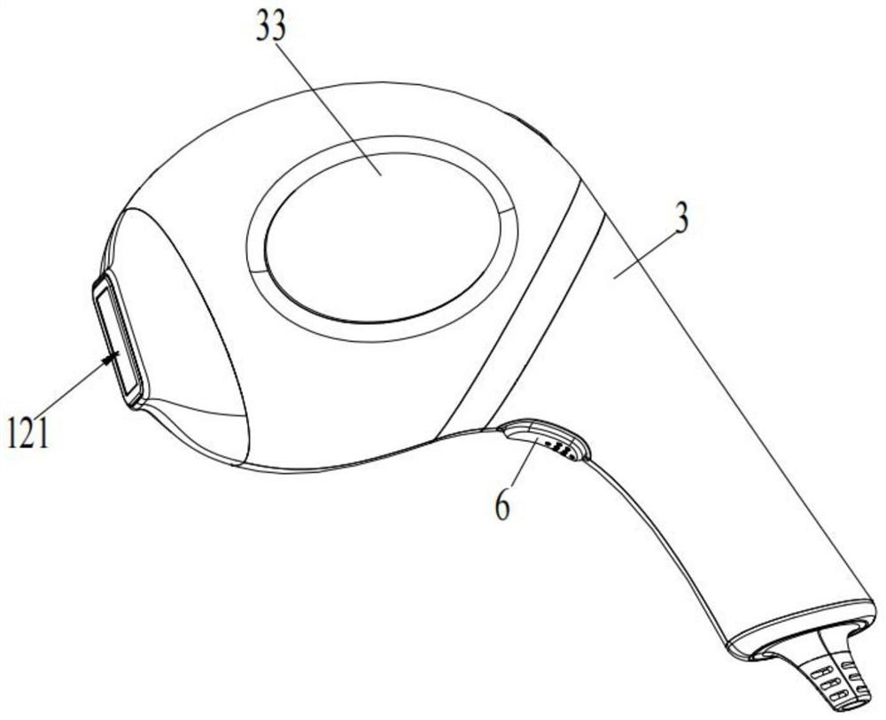
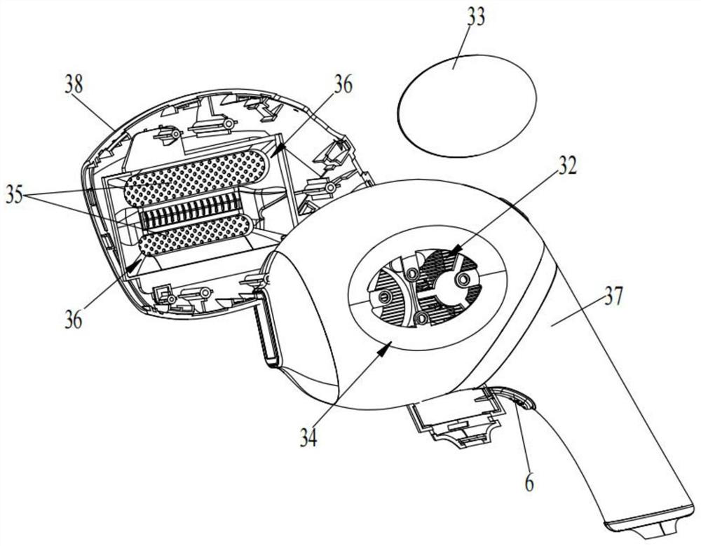
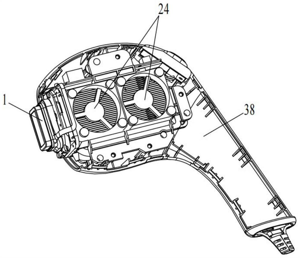
[0019] like Figure 1-Figure 8 As shown in , the present application proposes a laser hair removal device, which includes a laser assembly 1 and a heat dissipation assembly 2; the laser assembly 1 includes a laser chip 11, and the laser chip 11 is used to emit laser light; the heat dissipation assembly 2 includes: a chip holder 21...


PUM


Abstract

The invention provides a laser hair removal instrument, and the instrument comprises a laser assembly which comprises a laser chip, and the laser chip is used for emitting laser; the heat dissipation assembly comprises a chip fixing seat, and the laser chip is fixedly connected to one side of the chip fixing seat; the semiconductor refrigeration sheet is provided with a refrigeration surface and a heating surface, and the refrigeration surface is fixedly connected with the other side of the chip fixing seat; the heating surface is fixedly connected with the first radiator; according to the laser hair removal instrument, multi-stage heat dissipation can be achieved, heat dissipation is conducted on the laser chip through the semiconductor chilling plate firstly, then heat dissipation is conducted on the semiconductor chilling plate through the first heat dissipation device, the working temperature of the laser chip can be kept below the room temperature through the multi-stage heat dissipation mode, the laser chip can be kept in the best light emitting state, and the service life of the laser chip is prolonged. The photoelectric conversion efficiency of the laser chip is guaranteed, the depilation effect of the laser depilation instrument is further guaranteed, and the service life of the laser chip can be prolonged to a certain extent.

Description

technical field [0001] The present application relates to the technical field of medical equipment, and in particular, to a household laser hair removal device. Background technique [0002] The traditional home laser hair removal instruments use edge-emitting semiconductor lasers, and the light-emitting direction of the edge-emitting semiconductor lasers is parallel to the surface of the laser substrate. The photoelectric conversion rate of the laser is low, generally 10%; and the operating temperature of the laser is 35 ℃ and below, when the temperature exceeds 35 ℃, the photoelectric conversion rate of the laser will be lower, and it will be easier to burn; some laser hair removal devices use semiconductor cooling chips to dissipate heat, but semiconductor cooling chips are used to dissipate heat to the skin. Prevent the temperature of the skin from being too high when the laser is irradiating the skin. The semiconductor cooling film is not used to dissipate the heat of t...

Claims


Application Information

Patent Timeline
IPC IPC(8): A61B18/20
CPCA61B18/20A61B2018/00005A61B2018/00476
Inventor 魏广路
Owner 深圳市纬安共创生物科技有限公司
Learn More