LLC high-frequency transformer and assembling method

A high-frequency transformer and assembly method technology, applied in the field of transformers, can solve the problems of low work efficiency, low winding efficiency, large air gap, etc., and achieve the effect of improving winding and installation efficiency

Active Publication Date: 2022-06-17
HANGZHOU YOZEA ELECTRONICS
View PDF11 Cites 0 Cited by
  • Summary
  • Abstract
  • Description
  • Claims
  • Application Information

AI Technical Summary

Problems solved by technology

[0003] At present, the LLC high-frequency transformer needs to be manually completed, such as the winding of the coil. The coil of the transformer is generally divided into a main coil, a secondary coil and an additional coil. When winding the coil, it is necessary to manually wind the three coils on the frame. Low work efficiency; even with mechanical winding, the winding efficiency is relatively low
[0004] In addition, the iron cores commonly used in LLC high-frequency transformers are generally divided into E-shaped iron cores and straight-shaped iron cores. The straight-shaped iron cores are used to fill the gap between the two interlaced E-shaped iron cores. Larger air gap in the road, less efficient

Method used


Image

  • LLC high-frequency transformer and assembling method
  • LLC high-frequency transformer and assembling method
  • LLC high-frequency transformer and assembling method

Examples


Embodiment approach

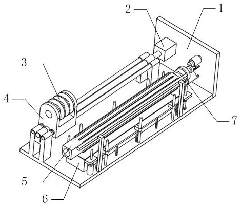
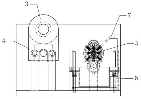
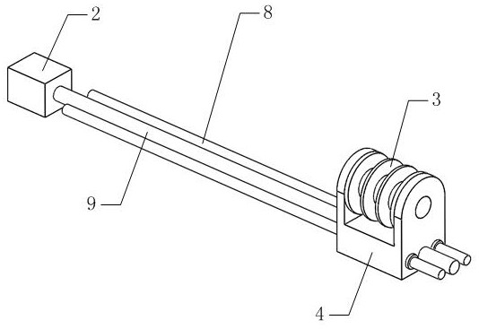
[0105] Embodiments: When using the transformer of the present invention, before assembling the transformer, coils need to be wound first.

[0106] The specific winding method is as follows: the first motor 2 and the third motor 21 are controlled to work, the third motor 21 will drive the mounting shell 19 to rotate, and the mounting shell 19 will rotate to drive the mounting inner shell 20, the first support slide 16 and the second support slide 17 spins. The first motor 2 works to drive the first threaded rod 9 to rotate, and the first threaded rod 9 drives the mounting slider 4 to slide under the action of the thread, and the sliding of the mounting slider 4 drives the winding wheel 3 to slide. While sliding along the two first guide sliding bars 8 , the winding wheel 3 is pulled and rotated by the rotating winding roller 5 through the wire resistance, and the wire resistance on the winding roller 5 is wound on the winding roller 5 . By controlling the first motor 2, the sl...


PUM


Abstract

The invention belongs to the technical field of transformers, and particularly relates to an LLC high-frequency transformer and an assembling method.The LLC high-frequency transformer comprises a frame body, a main coil, a secondary coil, an auxiliary coil and an E-shaped iron core, in order to enable a coil on a winding roller to be taken down from the winding roller smoothly, a first supporting sliding plate and a second supporting sliding plate are designed, and in the winding process, the coil on the winding roller can be taken down smoothly; the wire resistor is wound on a wire roller composed of the first supporting sliding plate and the second supporting sliding plate, and when the wire resistor is taken down, the first supporting sliding plate and the second supporting sliding plate are controlled to move inwards relative to the installation outer shell and the installation inner shell, so that the coil is separated from the first supporting sliding plate and the second supporting sliding plate, and the coil is taken down conveniently. And meanwhile, the mounting inner shell is controlled to slide back and forth relative to the mounting outer shell, and in the coil taking-down process, the first supporting sliding plate and the second supporting sliding plate slide relatively and generate vibration at the same time, so that coil taking-down is further facilitated.

Description

technical field [0001] The invention belongs to the technical field of transformers, and in particular relates to an LLC high-frequency transformer and an assembly method. Background technique [0002] With the development of modern power electronic technology and the birth of high-frequency switching devices, switching power supplies are developing towards high frequency, integration and modularization. LLC resonant converters are more and more widely used. [0003] At present, LLC high-frequency transformers need to be completed manually, such as winding of coils. The coils of transformers are generally divided into main coils, secondary coils and additional coils. When winding the coils, the three coils need to be manually wound on the frame body in turn. The work efficiency is low; even with mechanical winding, the winding efficiency is relatively low. [0004] In addition, the iron cores often used in LLC high-frequency transformers are generally divided into E-shaped...

Claims


Application Information

Patent Timeline
Patent Type & Authority Applications(China)
IPC IPC(8): H01F27/30H01F41/06
CPCH01F27/306H01F41/06Y02B70/10
Inventor 陈谷峰郭芳平桂宏正聂代文
Owner HANGZHOU YOZEA ELECTRONICS
Why Eureka
Try Eureka