Multidirectional head traction device

A traction device and head technology, which is applied in the field of multi-directional head traction devices, can solve the problem that the traction frame cannot rotate, etc.

Pending Publication Date: 2022-06-21
王顺有
View PDF0 Cites 0 Cited by
  • Summary
  • Abstract
  • Description
  • Claims
  • Application Information

AI Technical Summary

Problems solved by technology

[0004] In order to solve the deficiencies of the prior art, the purpose of the present invention is to provide a multi-directional head traction device, which can achieve multiple angles of traction on the patient's head, and can solve the problem of traditional fixed traction when the patient changes from a supine position to a prone position. The problem that the rack cannot rotate

Method used


Image

  • Multidirectional head traction device
  • Multidirectional head traction device
  • Multidirectional head traction device

Examples


Embodiment 1

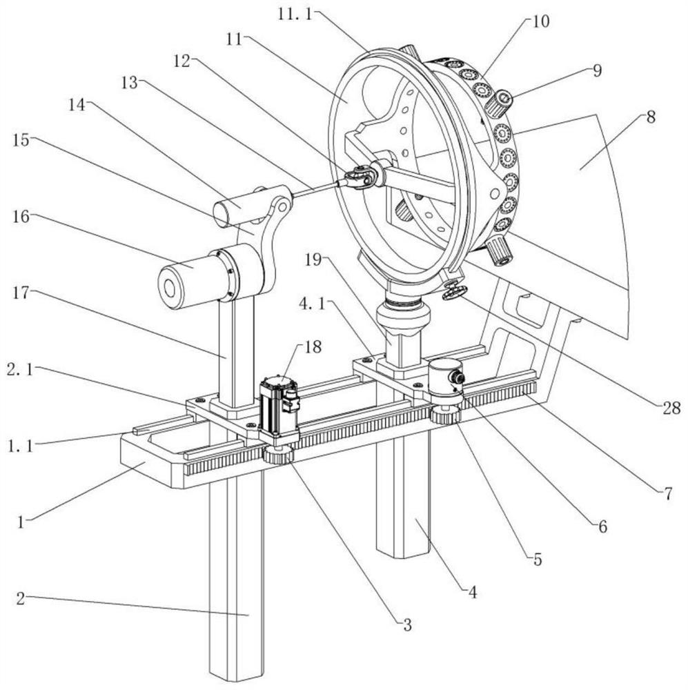
[0034] Embodiment 1: The cage 10 is provided with a plurality of threaded holes 10.1 at equal intervals in the circumferential direction. According to the actual situation of different patients, appropriate positioning points can be adopted to fix the patient's head with four skull nails 27 .

Embodiment 2

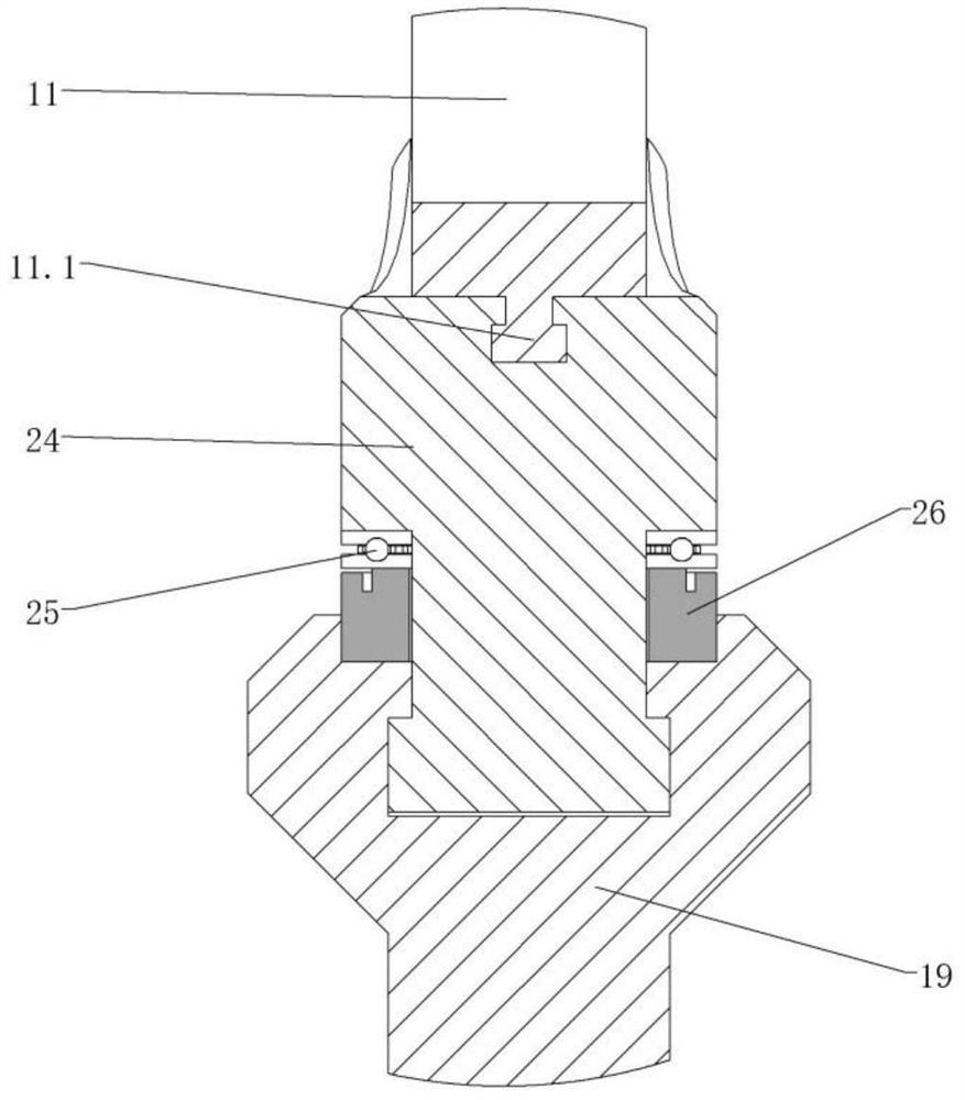
[0035] Embodiment 2: The cage 10 has five degrees of freedom in space, wherein the cage 10 is rotatably connected with the turret 11 to form a horizontal axis rotation degree of freedom, and the rotatable connection between the turret 11 and the chute frame 24 constitutes a longitudinal axis rotation degree of freedom, and the chute The frame 24 and the second lifting column 19 are rotationally connected to form the degree of freedom of the vertical axis rotation, the lifting action of the second lifting column 19 forms the degree of freedom of the vertical axis movement, and the forward and backward movement of the second guide cylinder 4 forms the degree of freedom of the vertical axis movement; rich freedom The degree can make the cage 10 realize multi-directional traction to the patient's head.

Embodiment 3

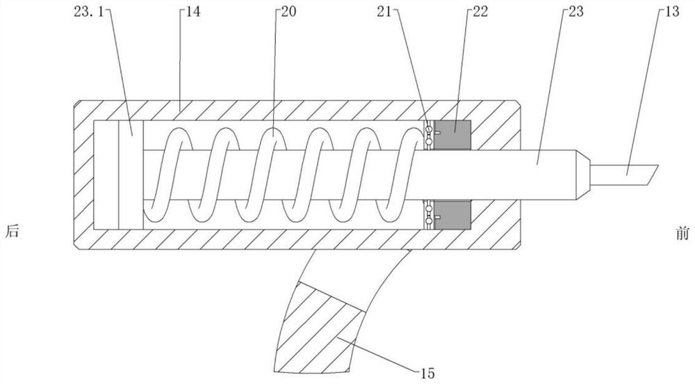
[0036] Embodiment 3: The servo motor 18 drives the first guide cylinder 2 to move backward so that the wire rope 13 can pull the cage 10; when the steering frame 15 is in a vertical state and the traction cylinder 14 is coaxial with the turret 11 , can realize longitudinal axis traction to patient's head; ; When the steering frame 15 is in a vertical state and the traction cylinder 14 is lower than the axis of the turret 11, the cage 10 can be deflected downward, and then the patient's head can be biased downward; when the steering frame 15 turns left After moving, the chute frame 24 and the holder 10 can be deflected to the left, and then the patient's head can be leftwardly pulled; when the steering frame 15 is rotated to the right, the chute frame 24 and the holder 10 can be turned Deflection to the right, and then the traction of the patient's head to the right is realized.


PUM


Abstract

According to the multidirectional head traction device, a supporting frame is fixedly connected with an operating bed, a servo motor can achieve traction of the head of a patient, a first lifting column can move up and down and be positioned, a direction adjusting frame is installed at the upper end of the first lifting column and forms a rotating pair, and a direct drive motor can achieve rotation and positioning of the direction adjusting frame. The traction cylinder is installed at the upper end of the direction adjusting frame and forms a rotating pair, the moving rod is coaxially installed in the traction cylinder and can move front and back and rotate, the first pressure sensor installed in the traction cylinder can monitor the traction force in real time, and the second lifting column can move up and down and be positioned. The holder is installed at the upper end of the second lifting column through a rotating frame and a sliding groove frame, the holder has five spatial freedom degrees and is connected with the head of a patient through a plurality of skull nails, the steel wire rope connects the moving rod with the holder, the torsion column can be coaxially installed with the skull nails in a nested mode, and the skull nails cannot loosen or fall off.

Description

technical field [0001] The invention relates to the technical field of medical instruments, in particular to a multidirectional head traction device. Background technique [0002] With the development of society and human progress, there are more and more patients with cervical spine injuries caused by traffic accidents, high-altitude falls and other reasons. Cervical spine injuries are common acute, critical and serious diseases, especially cervical spine fractures with Dislocation and spinal cord injury are life-threatening and high-level paraplegia is possible at any time; as we all know, cervical spine surgery is difficult and risky, and the requirements for each surgical link are very high. Disabled, severe then causes the rapid death of the patient. [0003] Head traction is the first choice for the clinical treatment of cervical vertebral fractures and dislocations, especially for patients with spinal cord injuries. It is also an important means of preoperative and i...

Claims


Application Information

Patent Timeline
Patent Type & Authority Applications(China)
IPC IPC(8): A61B17/66
CPCA61B17/66A61B17/645
Inventor 王顺有
Owner 王顺有
Why Eureka
Try Eureka