
Tension type shaped charge blasting device

A technology of energy accumulation and tensioning, which is applied in the field of tensioning energy-forming blasting devices, can solve the problems of dislocation of circular motion, imperfect technology, unstable direction of energy jet, etc., and achieves the effect of increasing the resistance to rotation and making the device convenient.

Active Publication Date: 2022-06-21
ANHUI UNIV OF SCI & TECH
View PDF10 Cites 0 Cited by
  • Summary
  • Abstract
  • Description
  • Claims
  • Application Information

AI Technical Summary

Problems solved by technology

[0004] The purpose of the present invention is to provide a tension-type energy-gathering blasting device to solve the problem that the current energy-gathering blasting devices on the market proposed by the above-mentioned background technology cannot meet people's needs due to relatively imperfect technology. After the energy-gathering device is embedded in the blasthole in practical applications, the size of the energy-gathering frame cannot be completely fitted with the size of the blasthole, which will cause circular motion or misalignment when the detonator is detonated, resulting in the direction of the energy jet being different. Stability, which makes cross-sectional blasting less effective

Method used


Image

  • Tension type shaped charge blasting device
  • Tension type shaped charge blasting device
  • Tension type shaped charge blasting device

Examples


Embodiment Construction

[0029] The technical solutions in the embodiments of the present invention will be clearly and completely described below with reference to the accompanying drawings in the embodiments of the present invention. Obviously, the described embodiments are only a part of the embodiments of the present invention, but not all of the embodiments. Based on the embodiments of the present invention, all other embodiments obtained by those of ordinary skill in the art without creative efforts shall fall within the protection scope of the present invention.

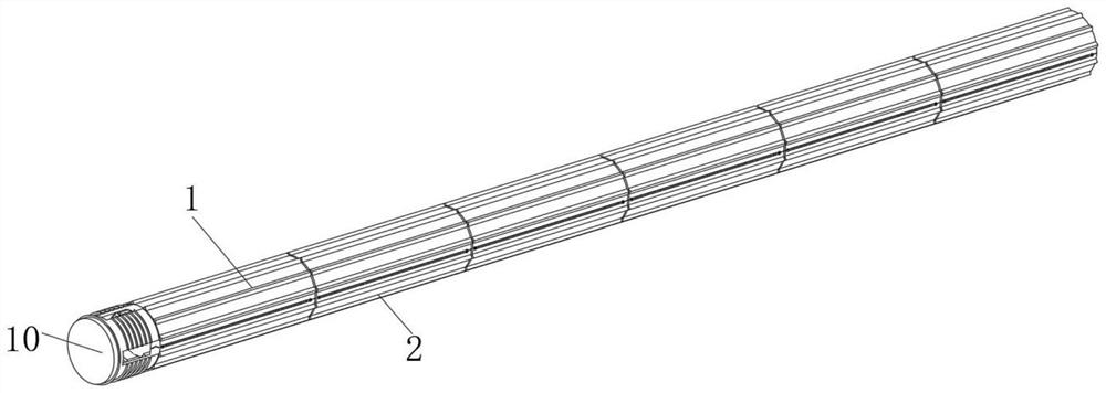
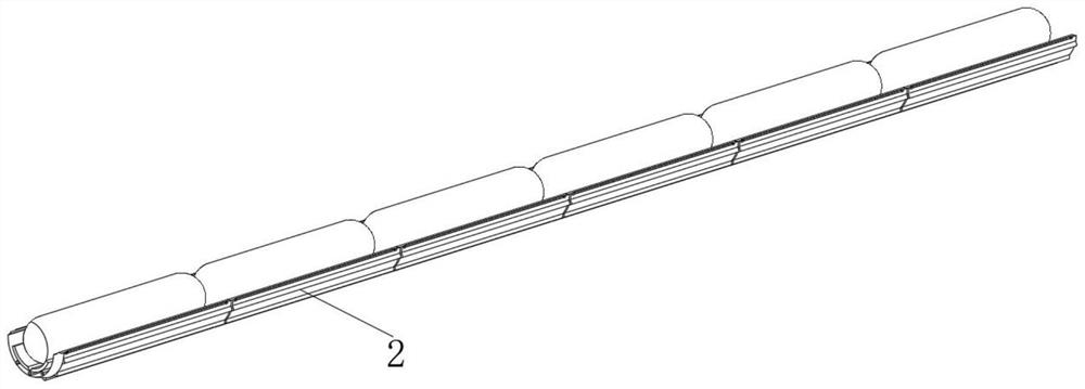
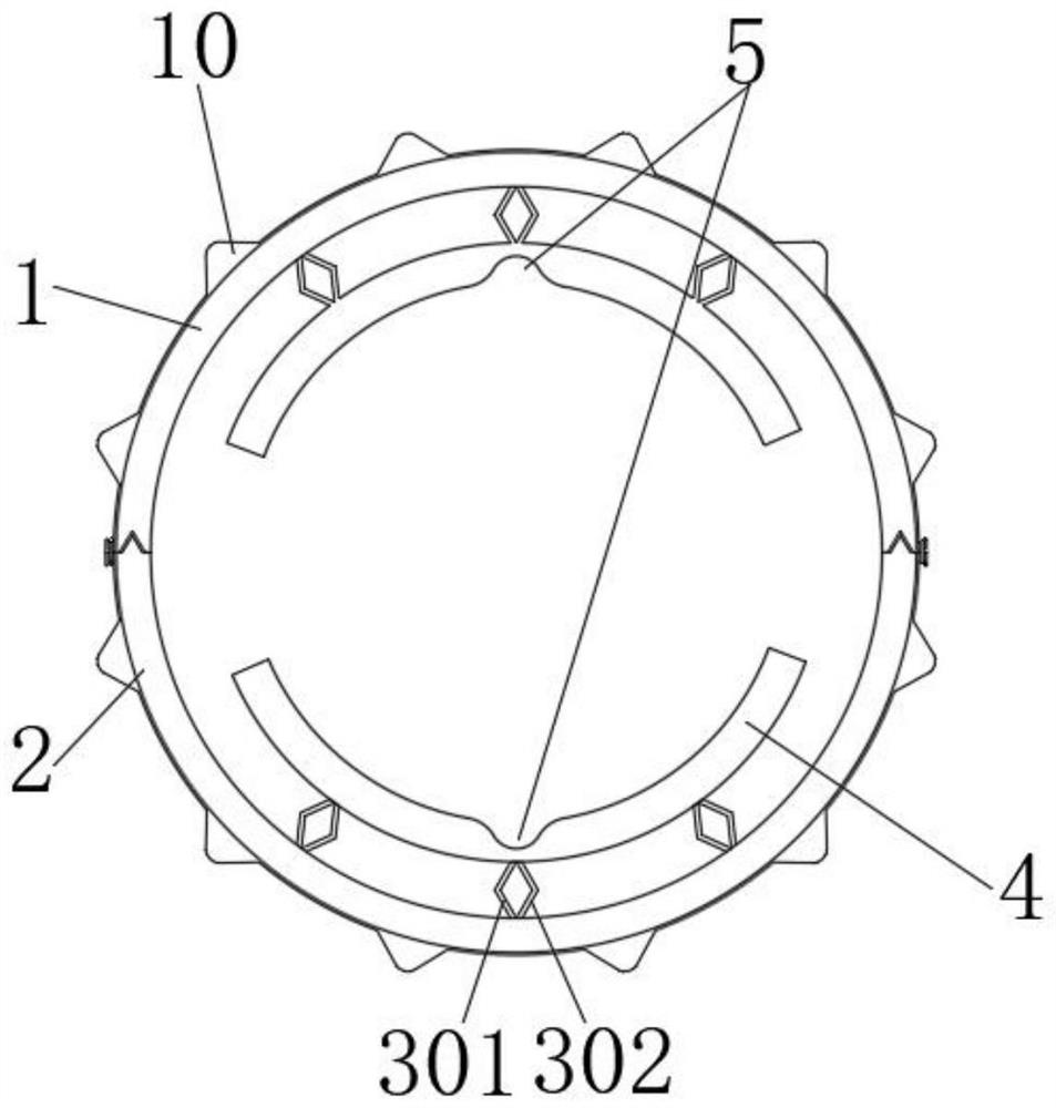
[0030] see Figure 1-10 , the present invention provides a technical solution: a tension-type energy-gathering blasting device, comprising a first energy-gathering frame 1, a first limit groove 101, a second energy-gathering frame 2, a limit block 201, a support frame 3, Placement frame 4, groove 5, connection buckle 6, second limit groove 601, rubber ring 7, cut surface 8, first concave surface 9, tensioning convex strip 10, tensioni...


PUM


Abstract

The invention discloses a tensioning type energy-gathered blasting device which comprises a first energy-gathered frame, an inclined face and a vertical face, a first limiting groove is formed in the bottom face of the first energy-gathered frame, a limiting block is arranged on the top face of a second energy-gathered frame, and a supporting frame comprises a first supporting strip and a second supporting strip. The first supporting strip and the second supporting strip are symmetrically arranged, the top end of the first energy gathering frame and the top end of the second energy gathering frame are connected with tensioning blocks, and tensioning pieces are arranged on the tensioning blocks. According to the tensioning type energy-gathered blasting device, when the explosive detonator is detonated, energy jet flow is sprayed out through the space between the first energy-gathered frame and the second energy-gathered frame, the tensioning protruding strips are evenly distributed on the first energy-gathered frame and the second energy-gathered frame, and when the tensioning protruding strips and the inner wall of a blast hole are in a tensioning state, the energy jet flow is ejected out through the space between the first energy-gathered frame and the second energy-gathered frame. And the rotation stopping force is increased through the tensioning convex strips, so that the problem that the blasting effect is poor due to the fact that the energy jet flow direction is affected by rotation displacement at the moment of blasting is solved.

Description

technical field [0001] The invention relates to the technical field of blasting, in particular to a tension-type energy-gathering blasting device. Background technique [0002] Blasting is a technology that uses the compression, loosening, destruction, throwing and killing effects of explosives in air, water, soil and rock media or objects to achieve the intended purpose. The scope of research includes: the properties and use methods of explosives and firearms, the explosive effect of charges in various media, the contact blasting and non-contact blasting of charges on targets, and the organization and implementation of various blasting operations. The steps of the blasting operation are to drill the blast hole or the excavated chamber or lay explosives on the surface of the medium to be blasted, put in the detonator, and then detonate. According to the shape of the charge and the way of charging, the blasting methods are mainly divided into three categories: the blast hole...

Claims


Application Information

Patent Timeline
IPC IPC(8): F42D1/00F42D1/22
CPCF42D1/00F42D1/22Y02P70/10
Inventor 朱群龙汪泉李志敏李瑞张军方敬贤刘志宇李泽华
Owner ANHUI UNIV OF SCI & TECH
Learn More