Inter-axis distance measurer and image forming apparatus

An inter-axis distance and measuring device technology, which is applied in the direction of measuring devices, image communication, and electrical devices, etc., can solve the problems of difficulty in measuring the distance between axes, lack of sufficient space, and inability to follow.

Pending Publication Date: 2022-06-21
KONICA MINOLTA INC
View PDF1 Cites 0 Cited by
  • Summary
  • Abstract
  • Description
  • Claims
  • Application Information

AI Technical Summary

Problems solved by technology

[0005] However, in the finished product, there is not enough space around the axis of the measurement object, and the measuring device cannot be arranged smoothly, and the distance between the axes cannot be measured.
[0006] In addition, when the axis moves like the fixing unit of the image forming apparatus, and furthermore, when it is desired to measure the change of the inter-axis distance following the movement, it is difficult to measure the inter-axis distance.
Measuring the distance between shafts is extremely difficult if there is not enough space around the shaft and the shaft moves
[0007] In the case of using the structure described in Patent Document 1 or other optical measurement units such as a laser length measuring device, it is necessary to be able to install an emitter and a light receiver, and it is necessary that there is no object other than the measurement object that blocks light on the optical path of the measurement light. conditions, so it is difficult to solve the above problems
According to the optical measuring unit, it is possible to follow the change of the inter-axis distance, but if the axis of the measurement object deviates from the irradiation range of the measurement light, it cannot follow
In order to increase the tracking range, it is necessary to increase the irradiation range and the light receiving range, so the size of the device is increased, and space is required around it.
[0008] In addition, when a measurer uses a hand-held measuring device such as a caliper, a micrometer, or a vernier caliper to perform measurement, the measurer needs to enter the device with his hand and transport the measuring device to the measurement position so that the measurement operation can be performed. Conditions that hinder measurement operations, etc., and the ability to measure correctly depends on the proficiency of the measurer, so there is also a problem that the measured value is unstable

Method used


Image

  • Inter-axis distance measurer and image forming apparatus
  • Inter-axis distance measurer and image forming apparatus
  • Inter-axis distance measurer and image forming apparatus

Examples


no. 1 approach

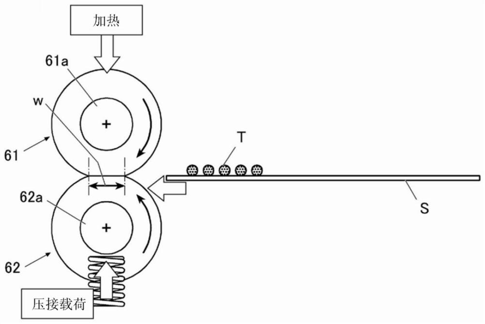
[0063] Figure 4 Two axes 61a, 62a of the measurement object are shown. One shaft 61 a is a core material constituting the shaft of the upper roll 61 . The other shaft 62a is a core material constituting the shaft of the lower roll 62 . like Figure 4 As shown, the distance between the two axes 61a and 62a is set as the measurement object, and the inter-axis distance measuring device 90 is set in the state at the time of measurement.

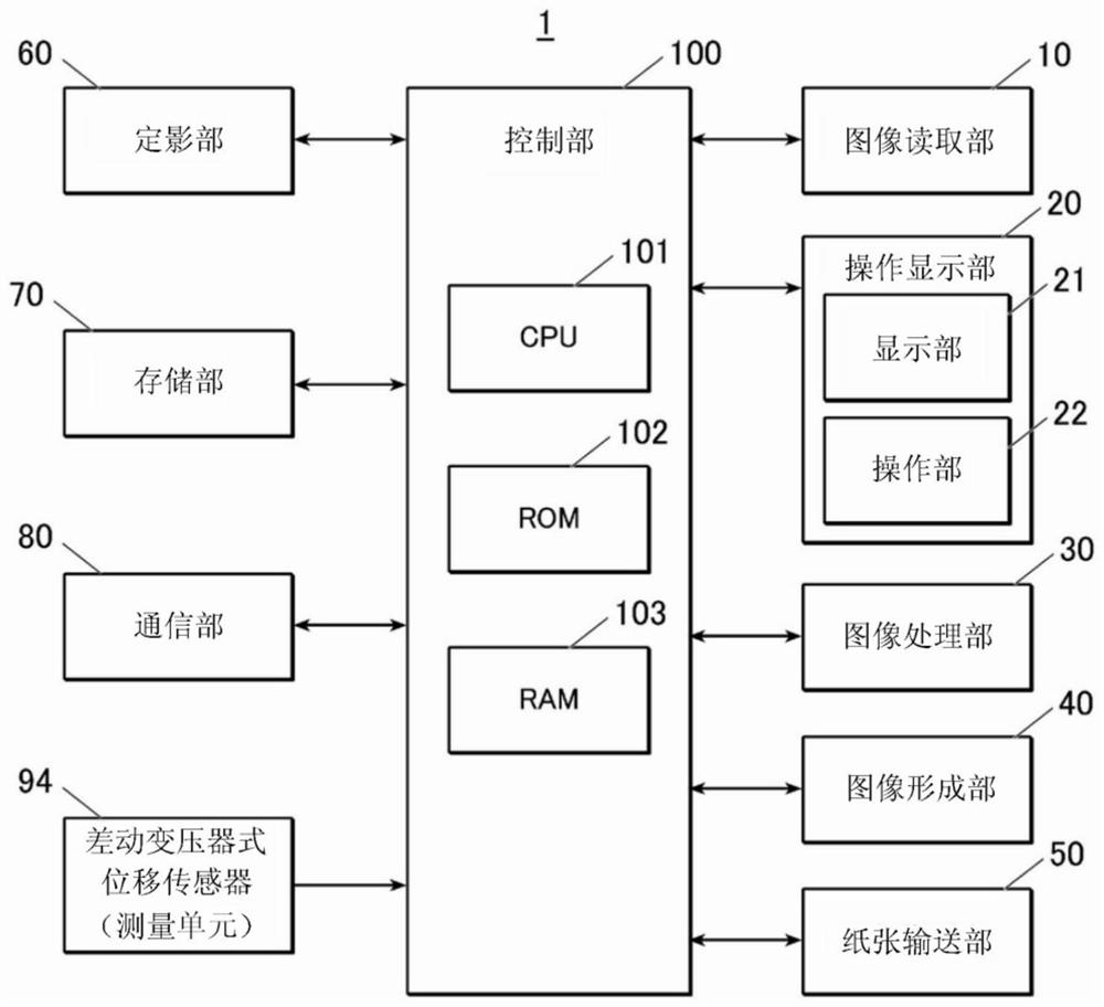
[0064] The inter-axis distance measuring instrument 90 is an inter-axis distance measuring instrument for measuring the distance between two axes or the displacement amount of the distance, and includes a first measuring head 91, a second measuring head 92, a linear moving mechanism (moving mechanism) 93, and Measurement unit (94).

[0065] The first measuring head 91 abuts on the peripheral surface 61c of one of the two shafts 61a and 62a during measurement, and serves as one measurement reference.

[0066] The second measurement head 92 c...

no. 2 approach

[0094] Hereinafter, an embodiment of a modified example based on the above-described first embodiment will be described. The same parts are denoted by the same reference numerals, and descriptions thereof are omitted.

[0095] Here, refer to Figure 8 The second embodiment will be described.

[0096] exist Figure 8 In the inter-shaft distance measuring device 90B shown, in the first measuring head 91 in contact with the peripheral surface 61c at two positions 91a, 91b, rolling bearings 91c, 91d are provided at each of the two positions 91a, 91b . As described above, the first measurement head 91 is in contact with the peripheral surface 61c of the shaft 61a at the two positions 91a and 91b. The abutting members are used as rolling bearings 91c and 91d.

[0097] exist Figure 8 In the inter-shaft distance measuring device 90B shown, the second measuring head 92 in contact with the peripheral surface 62c at two positions 92a and 92b is also provided with a rolling bearing...

no. 3 approach

[0100] Next, refer to Figure 9 A third embodiment will be described.

[0101] exist Figure 9 The shown inter-axis distance measuring device 90C includes an elastic connecting portion 62S for connecting either one of the first measuring head 91 and the second measuring head 92 (in the present embodiment, the second measuring head 92). The head 92) is fixed to the support frame 62F of the shaft 62a with which the one measurement head 92 is in contact with the measurement head 92 being pressed against the shaft 62a by the elastic force.

[0102]Approaching and separating operations of the two shafts 61a and 62a include a crimping and deviating stroke during operation of the image forming apparatus 1, and a stroke in which separation exceeds the maximum distance of the crimping and deviating stroke for maintenance and the like (hereinafter referred to as a stroke). "Open Stroke"). The crimping and deviating strokes are ranges that vary according to the driving force. The lin...


PUM


Abstract

The invention provides an inter-axis distance measuring device which can be installed in a space-saving manner, and can stably measure the inter-axis distance with high precision along with the change of the inter-axis distance. The inter-axis distance measurer is provided with: a first measuring head which is brought into contact with the circumferential surface of one of the two axes during measurement and serves as one measurement reference; a second measuring head which is in contact with the circumferential surface of the other one of the two shafts during measurement and serves as the other measuring reference; a moving mechanism which includes an elastic member, supports the first measuring head and the second measuring head in a relative movement manner, and applies a force in a direction in which the first measuring head and the second measuring head are separated by an elastic force of the elastic member; and a measuring unit configured to measure a displacement based on a distance between the first measuring head and the second measuring head of the moving mechanism. The inter-axis distance measurer can be maintained in a measurement state in which a first measuring head and a second measuring head, which are inserted between two axes, exert a pressing force on the two axes in a direction extending between the two axes by means of a movement mechanism.

Description

technical field [0001] The present invention relates to an inter-axis distance measurer and an image forming apparatus. Background technique [0002] In an apparatus having a roller pair, such as an image forming apparatus, the inter-axis distance between one shaft and the other shaft constituting the roller pair affects the processing performance of the apparatus, so it is necessary to measure each finished product. [0003] Patent Document 1 describes an inter-axis distance measurement unit composed of a light-emitting element (light-emitting diode) and a light-receiving element (photodiode). The inter-axis distance measuring units are respectively fixed so that the light irradiated from the light-emitting diodes strikes one of the two axes constituting the roller pair, and the reflected light thereof is incident on the photodiodes, according to the change in the intensity of the reflected light accompanying the movement of the axis to measure the distance between axes. ...

Claims


Application Information

Patent Timeline
Patent Type & Authority Applications(China)
IPC IPC(8): G01B11/14G03G21/16
CPCG01B11/14G03G21/16H04N1/00042H04N1/00034H04N1/00082G01B5/14G01B7/14G01D5/2291G01B7/02
Inventor 渡边义章桥村嘉人藤山大助
Owner KONICA MINOLTA INC
Why Eureka
Try Eureka