High-pressure-resistant and corrosion-resistant remote transmission differential pressure sensor

A corrosion-resistant and high-pressure-resistant technology, which is applied to the measurement of pressure difference between multiple valves, instruments, and measurement of fluid pressure. problems, to achieve the effect of improving water pressure resistance and overall reliability

Pending Publication Date: 2022-06-21
中国船舶集团有限公司第七零七研究所九江分部
View PDF6 Cites 0 Cited by
  • Summary
  • Abstract
  • Description
  • Claims
  • Application Information

AI Technical Summary

Problems solved by technology

[0003] However, the traditional differential pressure sensor usually does not have the overall pressure resistance capability, and the pressure-taking diaphragm does not have protection facilities. Its measurement components and capillary tubes usually need to be installed in a space with good environmental conditions, and only the diaphragm is in direct contact with the fluid to be measured. This has caused it to be unable to adapt to harsh environments such as deep seas without closed spaces, even if the use has limitations
In addition, the length of the capillary of a traditional differential pressure sensor usually does not exceed 10m. As the capillary lengthens, the pressure measurement accuracy of the sensor decreases accordingly.

Method used


Image

  • High-pressure-resistant and corrosion-resistant remote transmission differential pressure sensor
  • High-pressure-resistant and corrosion-resistant remote transmission differential pressure sensor
  • High-pressure-resistant and corrosion-resistant remote transmission differential pressure sensor

Examples


Embodiment Construction

[0045] The technical solutions in the embodiments of the present invention will be clearly and completely described below with reference to the accompanying drawings in the embodiments of the present invention. Obviously, the described embodiments are only a part of the embodiments of the present invention, but not all of the embodiments. Based on the embodiments of the present invention, all other embodiments obtained by those of ordinary skill in the art without creative efforts shall fall within the protection scope of the present invention.

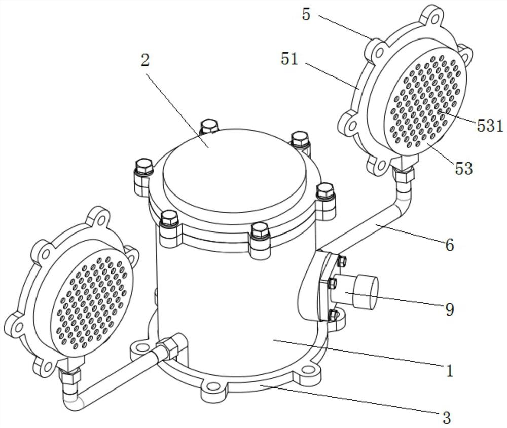
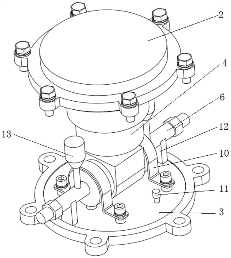
[0046] The embodiment of the present invention discloses a high-pressure and corrosion-resistant remote differential pressure sensor, comprising:

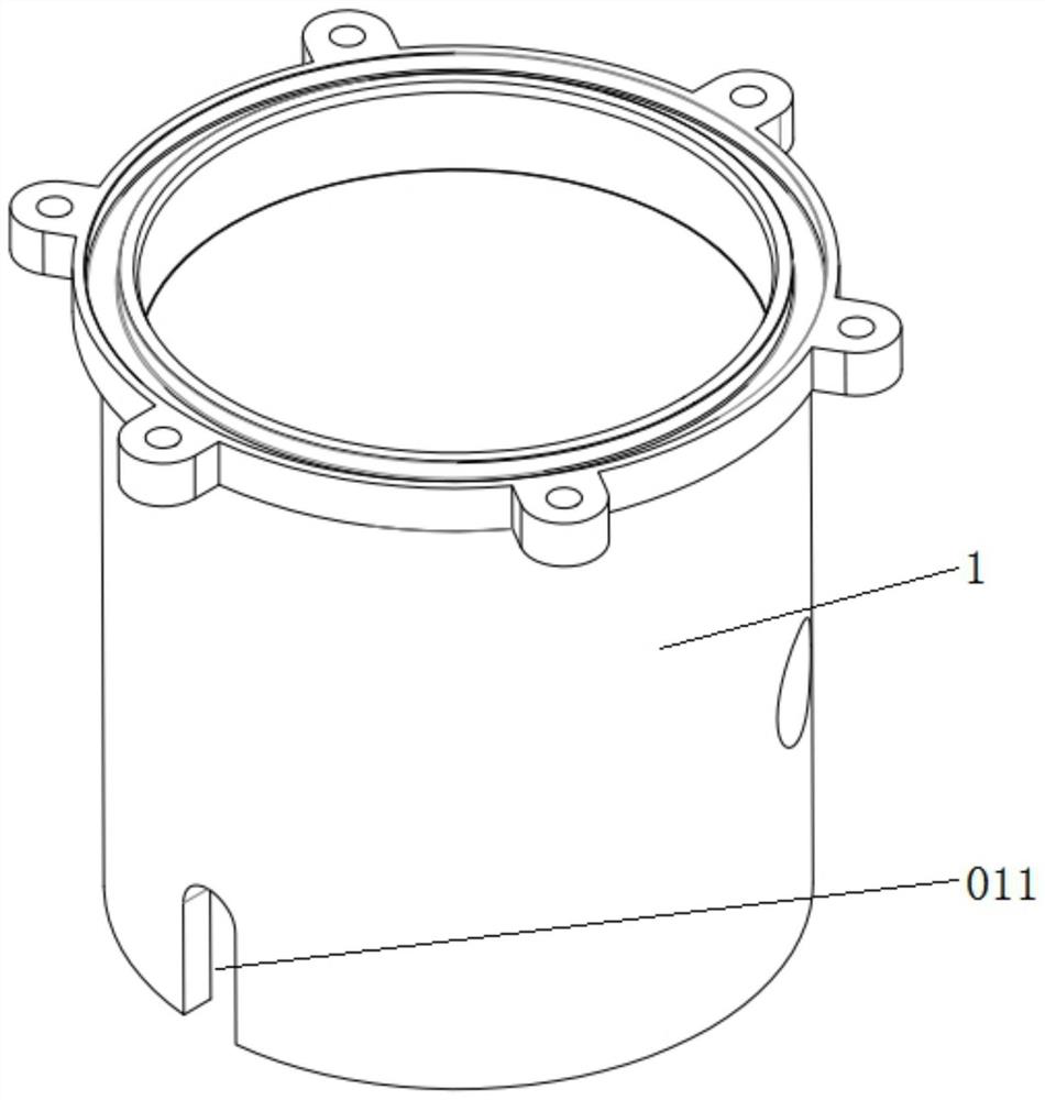
[0047] Cylinder 1, both ends of the cylinder 1 are open;

[0048] The cylinder cover 2, the cylinder cover 2 is fixed on the top of the cylinder body 1;

[0049] The bottom of the cylinder 3, the bottom of the cylinder 3 is fixed on the bottom of the cylinder body 1;

[0050] The measuri...


PUM


Abstract

The invention discloses a high-pressure-resistant and corrosion-resistant remote transmission differential pressure sensor. The sensor comprises a cylinder, wherein the two ends of the cylinder are open; the cylinder cover is fixed at the top of the cylinder body; the cylinder bottom is fixed at the bottom of the cylinder body; the measuring assembly is arranged in the cylinder body and is fixedly connected with the cylinder bottom; the two pressure tapping accessories are located on the two sides of the cylinder respectively and connected with the two pressure measuring ends of the measuring assembly. The pressure tapping accessory comprises a mounting flange, a diaphragm and a protective cover; the diaphragm is fixed on the surface of the mounting flange, the protective cover is fixedly connected with the mounting flange, and the diaphragm is arranged in the protective cover; a plurality of through holes are formed in the surface of the protective cover; the capillary tube is wrapped with a layer of protective sleeve; the two capillary tubes are connected to the two pressure measuring ends of the measuring assembly respectively. One end of the capillary tube penetrates through the side wall of the cylinder and is fixedly connected with the pressure measuring end of the measuring assembly, and the other end is fixedly connected with the diaphragm. The pressure difference sensor can be used for deep sea operation, has high pressure resistance and corrosion resistance, and is accurate in measured data.

Description

technical field [0001] The invention relates to the technical field of sensors, in particular to a high-pressure-resistant and corrosion-resistant remote differential pressure sensor. Background technique [0002] The existing remote differential pressure sensor is mainly composed of measuring components, mounting flanges, capillaries, etc. The mounting flanges include static pressure and full pressure diaphragms, which are respectively connected to the static pressure and full pressure ends of the measuring components through the capillaries. The two pressure differences are converted into electrical signals, and after processing, they are transmitted to users using 4-20Ma standard signals. [0003] However, traditional differential pressure sensors usually do not have the overall pressure resistance capability, and the pressure-taking diaphragm does not have protective facilities. The measuring components and capillaries usually need to be installed in a space with good en...

Claims


Application Information

Patent Timeline
Patent Type & Authority Applications(China)
IPC IPC(8): G01L13/00G01L19/00G01L19/06
CPCG01L13/00G01L19/0046G01L19/0672G01L19/0627G01L19/0654
Inventor 罗鑫李光磊曹虎李雪璞石剑峰欧阳贤斌鲁妤知李方杨小明
Owner 中国船舶集团有限公司第七零七研究所九江分部
Why Eureka
Try Eureka