Frequency converter system input side fault protection method and control system
A technology of fault protection and frequency converter, applied in the field of frequency converter to achieve the effect of efficient operation
Pending Publication Date: 2022-06-21
常州捷驰达电子科技有限公司
View PDF0 Cites 0 Cited by
- Summary
- Abstract
- Description
- Claims
- Application Information
AI Technical Summary
Problems solved by technology
[0007] The purpose of the present invention is to provide a fault protection method and control system on the input side of the inverter system to solve the protection problem when the input side fault occurs during the operation of the inverter system composed of multiple inverters
Method used
View moreImage
Smart ImageViewing Examples

Examples
Embodiment 1
Embodiment 2
Embodiment 3
Login to View More PUM
 Abstract
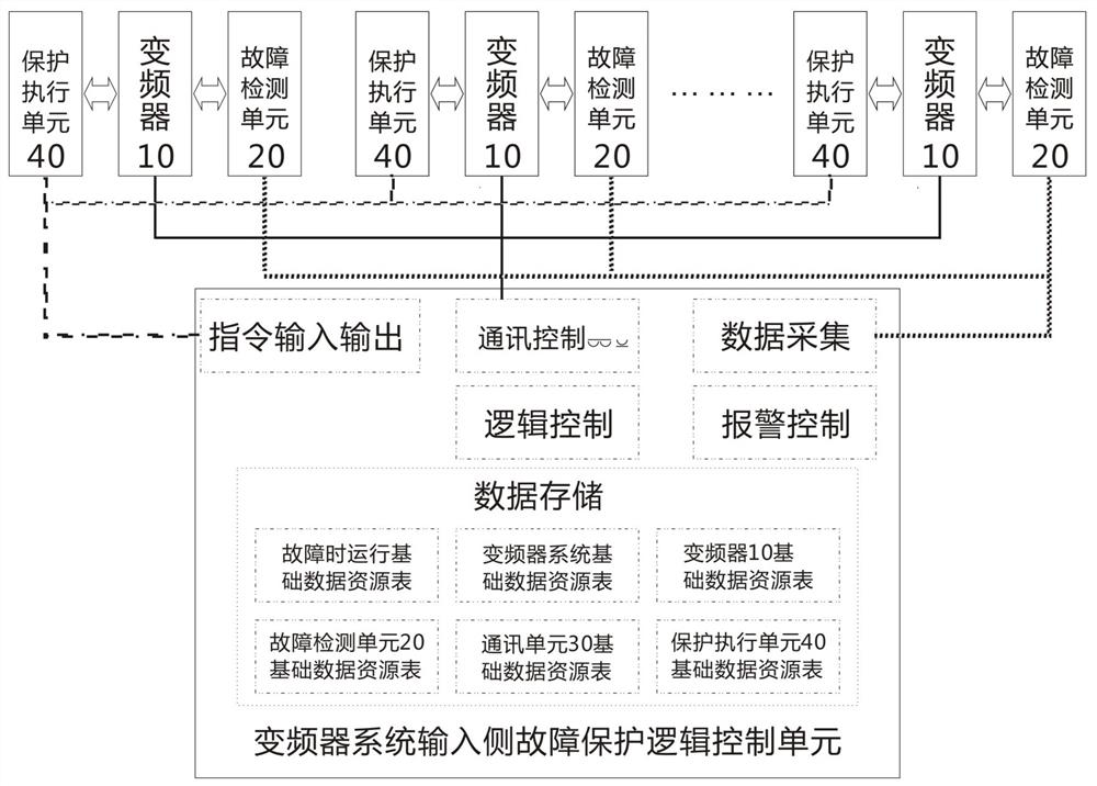
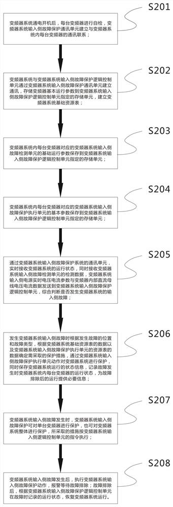
The invention discloses a frequency converter system input side fault protection method and a control system, and the fault protection method comprises the steps: employing a breaking fault frequency converter and a fault unit according to different fault types when the input side of a frequency converter system has a partial fault, and guaranteeing the normal operation of the system; and when the system must be shut down due to the fault, storing the operating parameters when the fault occurs, and enabling each frequency converter in the system to be shut down in a coordinated and associated manner. The frequency converter system input side fault protection control system comprises a protection system communication unit, a fault detection unit, a logic control unit and a fault protection execution unit. Component parts in the fault protection system can be configured according to actual needs, and convenience and flexibility are achieved. Compared with the prior art, the method has the beneficial effects that effective protection and fault processing are carried out on the fault of the input side of the frequency converter system, the requirements of the frequency converter system are better met, and the safety of the frequency converter system and the reliability of system operation are improved.
Description
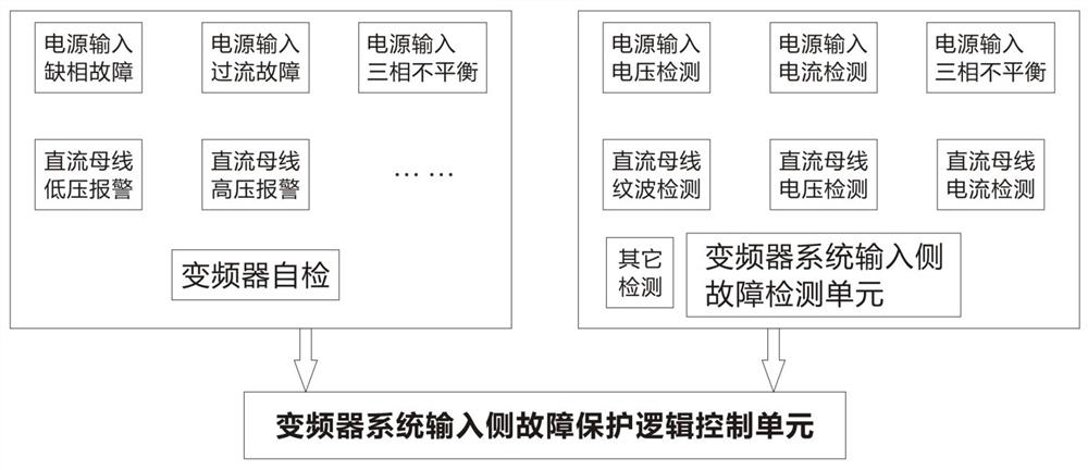
technical field [0001] The invention relates to the field of frequency converters, more specifically, to a fault protection method and a control system at the input side of a frequency converter system. Background technique [0002] At present, the frequency converter system composed of multiple frequency converters is more and more widely used in practical applications. Through the collaborative control of multiple inverters, the process requirements of complex production sites can be completed. The power supply of the inverter system can be provided individually for each inverter, or it can be supplied uniformly. In this way, when dealing with faults on the input side of the system, it is necessary to distinguish between different situations for fault handling. [0003] During the normal operation of the inverter, the three-phase industrial frequency power supply is used. When the power grid fluctuates, such as a sudden loss of power in a short period of time or a short-t...
Claims
Login to View More Application Information
Patent Timeline
 IPC IPC(8): H02H7/12H02M1/32H02M1/34
CPCH02H7/1216H02M1/32H02M1/34
Inventor 唐宇
Owner 常州捷驰达电子科技有限公司
Features
- Generate Ideas
- Intellectual Property
- Life Sciences
- Materials
- Tech Scout
- Unparalleled Data Quality
- Higher Quality Content
- 60% Fewer Hallucinations
Learn More Browse by: Latest US Patents, China's latest patents, Technical Efficacy Thesaurus, Application Domain, Technology Topic, Popular Technical Reports.
© 2025 PatSnap. All rights reserved.Legal|Privacy policy|Modern Slavery Act Transparency Statement|Sitemap|About US| Contact US: help@patsnap.com