Automated analyzer

An automatic analysis device, a part of the technology, is applied in the direction of measurement device, analysis material, material analysis by optical means, etc., can solve the problems of reduced precision or accuracy, unable to obtain the quantitative effect of 2-wavelength measurement method, etc., and achieves clear effect. Effect

Pending Publication Date: 2022-06-21
HITACHI HIGH-TECH CORP
View PDF3 Cites 0 Cited by
  • Summary
  • Abstract
  • Description
  • Claims
  • Application Information

AI Technical Summary

Problems solved by technology

In this measurement method, it is assumed that the light of each wavelength matches the optical axis of the reaction solution with the light quantity distribution, and if they do not match, the quantitative effect with high precision inherent in the two-wavelength measurement method cannot be obtained.
For example, when a two-wavelength measurement method is performed using two wavelengths of light whose optical axes or light intensity distributions do not match, the precision or accuracy is significantly lowered due to the influence of noise such as air bubbles compared to the case where they match.

Method used


Image

  • Automated analyzer
  • Automated analyzer
  • Automated analyzer

Examples


Embodiment approach 1

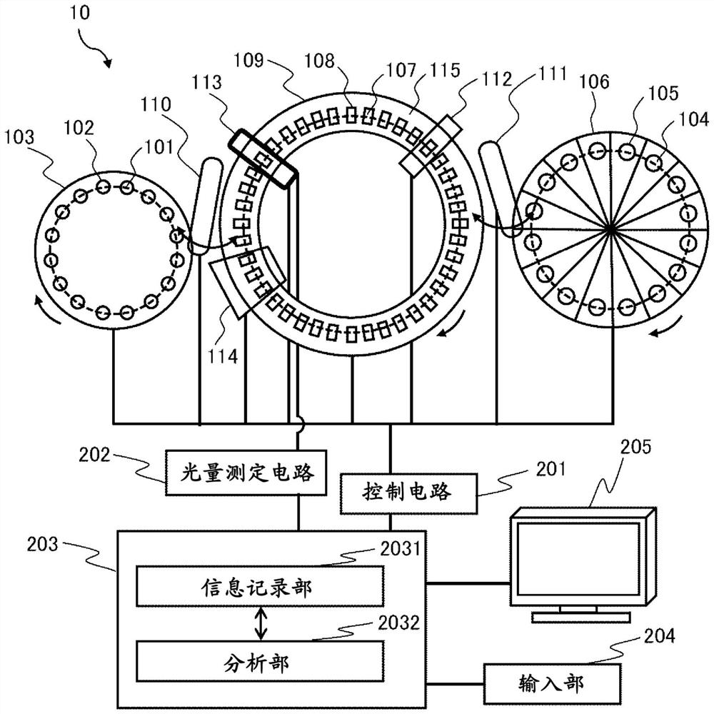
[0034] figure 1 It is a schematic diagram which shows the whole structure of the automatic analyzer 10 which concerns on Embodiment 1 of this invention. The automatic analyzer 10 performs measurement by irradiating a sample with light. The automatic analyzer 10 includes a sample disk 103 , a reagent disk 106 , a reaction disk 109 , a dispensing mechanism, a control circuit 201 , a light quantity measurement circuit 202 , a data processing unit 203 , an input unit 204 , and an output unit 205 .

[0035] The dispensing mechanism moves the sample and the reagent between the disks. The control circuit 201 controls each disk and the dispensing mechanism, and the light quantity measuring circuit 202 measures the absorbance of the reaction solution. The data processing unit 203 processes the data measured by the light quantity measurement circuit 202 . The input unit 204 and the output unit 205 are interfaces with the data processing unit 203 . The dispensing mechanism includes a...

Embodiment approach 2

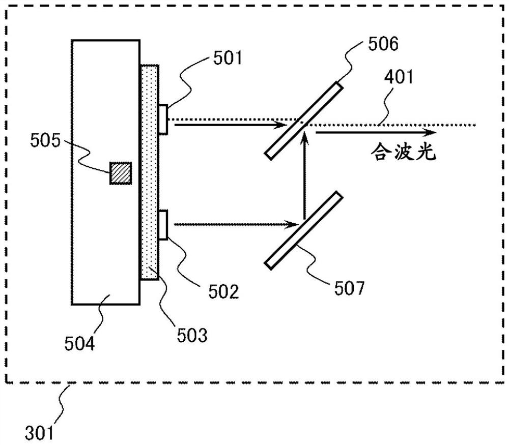
[0063] Figure 6A This is an example of the configuration of the light source unit 301 included in the automatic analyzer 10 according to Embodiment 2 of the present invention. In the second embodiment, by diffusing the emitted light of the second LED 502 , the light intensity distribution of the emitted light of the second LED 502 is made uniform on the light receiving surface of the light receiver of the spectroscope 302 . The other structures are the same as those of the first embodiment.

[0064] When the effective light-emitting area of ​​the LED light source is 1.0 mm square, it is necessary to design only the optical axis of the first LED 501 to coincide with the optical axis 401 incident on the beam splitter 302 in order to obtain a light quantity capable of quantitative analysis with high accuracy. However, in this case, it is difficult to make the outgoing optical axis of the second LED 502 coincide with the optical axis 401 entering the beam splitter 302 . In this...

Embodiment approach 3

[0080] In order to stably obtain the analytical performance of the absorption analysis of the automatic analyzer 10, it is preferable that the light quantity of the light source unit 301 is always constant. As means for keeping the amount of light constant, temperature control of the LED mounting board 503 and drive current control of the LEDs can be used. Therefore, in Embodiment 3 of the present invention, a control procedure for stabilizing the light quantity of the automatic analyzer 10 will be described. The configuration of the automatic analyzer 10 is the same as that of the first to second embodiments.

[0081] For example, as an LED that generates ultraviolet light with a wavelength of 340 nm or less, AlGaN crystal, which is a compound semiconductor, is used. In the case of using AlGaN crystal as the light-emitting layer, the luminous efficiency of the ultraviolet LED is a fraction to one tenth lower than that of the InGaN crystal used in the light-emitting layer of ...


PUM


Abstract

The purpose of the present invention is to provide an automatic analysis device capable of obtaining a stable amount of light over a wide wavelength band by multiplexing a plurality of LED lights, and capable of matching the temperature characteristics of each LED element. With reference to FIG. 3, this automatic analysis device is configured such that light emitted from a second LED is reflected and multiplexed with light emitted from a first LED on the same optical axis, and the first LED and the second LED are in contact with the same temperature adjustment member.

Description

technical field [0001] The present invention relates to an automatic analyzer for analyzing the amount of components contained in a sample. Background technique [0002] In an automatic analyzer for analyzing the amounts of components such as proteins, sugars, lipids, enzymes, hormones, inorganic ions, disease markers, etc. contained in biological samples such as blood and urine, a liquid storage container is usually divided into Samples and reagents are injected, and inspection items are analyzed based on changes in optical properties such as absorbance, fluorescence, and luminescence. In the absorption analysis of an automatic analyzer, a method is used in which light from a light source is irradiated to a sample or a reaction solution in which the sample and the reagent are mixed, and a single or multiple measurement wavelengths that have passed through the sample or the reaction solution are measured by a light-receiving element. The absorbance is calculated from the tr...

Claims


Application Information

Patent Timeline
Patent Type & Authority Applications(China)
IPC IPC(8): G01N21/01G01N21/03G01N21/27G01N21/33G01N35/00
CPCG01N21/3151G01N2021/3155G01N2021/3181G01N21/255H05B45/10G01N21/33G01N35/00584
Inventor 安藤贵洋足立作一郎气田康宏松冈裕哉森弘充今村伸高田英一郎荒井诚
Owner HITACHI HIGH-TECH CORP
Why Eureka
Try Eureka