Waste gas treatment device of thermal power plant

A waste gas treatment device and thermal power plant technology, applied in the direction of combined devices, transportation and packaging, separation methods, etc., can solve the problems of wasting water resources, low filtration efficiency, easy clogging of filter nets, etc., and achieve the goal of preventing clogging and improving filtering effect Effect

Pending Publication Date: 2022-06-24
DATANG HUAYIN ELECTRIC POWER
View PDF0 Cites 2 Cited by
  • Summary
  • Abstract
  • Description
  • Claims
  • Application Information

AI Technical Summary

Problems solved by technology

[0005] The technical problem to be solved by the present invention is to provide a waste gas treatment device for a thermal power plant to solve the problems that the existing filter screen is easy to block, the filtration efficiency is low, the purified water needs to be replaced frequently and flocculants are added, the work is cumbersome, and water resources are wasted.

Method used


Image

  • Waste gas treatment device of thermal power plant
  • Waste gas treatment device of thermal power plant
  • Waste gas treatment device of thermal power plant

Examples


Embodiment Construction

[0031] In order to make the technical problems, technical solutions and advantages to be solved by the present invention more clear, the following will be described in detail with reference to the accompanying drawings and specific embodiments.

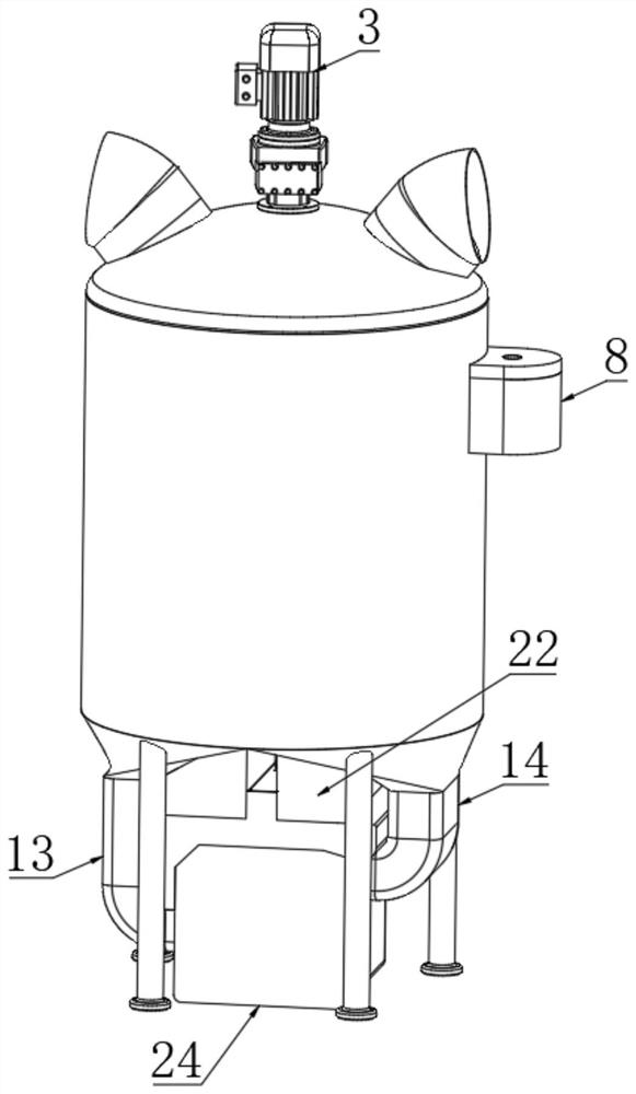
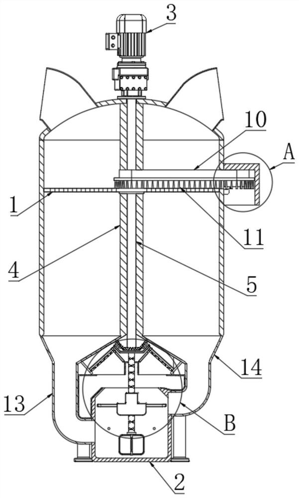
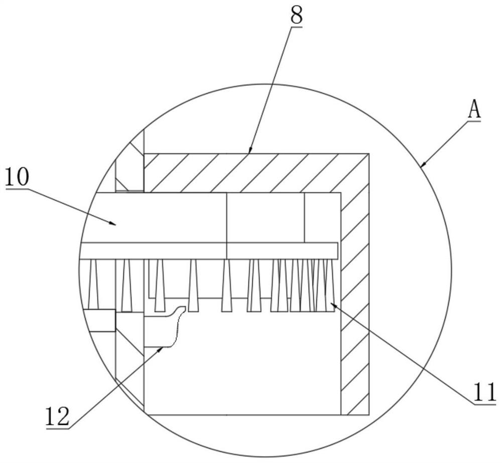
[0032] like figure 1 and figure 2As shown, the embodiment of the present invention provides an exhaust gas treatment device of a thermal power plant, including an exhaust gas treatment tank, the top end of the exhaust gas treatment tank is respectively provided with an air inlet and an air outlet, and the bottom end of the exhaust gas treatment tank is provided with a support leg , a motor 3 is installed on the top of the exhaust gas treatment tank, a partition 4 is arranged inside the exhaust gas treatment tank, and a rotating shaft 5 is arranged inside the partition 4 corresponding to the axial position of the exhaust gas treatment tank, and the output end of the motor 3 passes through the exhaust gas treatment tank. The top of th...


PUM


Abstract

The invention provides a waste gas treatment device of a thermal power plant, and belongs to the technical field of waste gas treatment. Comprising a waste gas treatment tank, a motor is installed at the top end of the waste gas treatment tank, a partition plate is arranged in the waste gas treatment tank, and a rotating shaft is arranged at the position, corresponding to the axis of the waste gas treatment tank, in the partition plate. The interior of the waste gas treatment tank is arranged into the U-shaped airflow channel through the partition plate, so that waste gas firstly descends and is physically filtered after entering the waste gas treatment tank, then the waste gas is introduced into the bottom of the waste gas treatment tank and is chemically filtered, and the waste gas ascends and is discharged from the gas outlet after being filtered, so that the waste gas treatment work is completed; through the circulation mode that waste gas firstly descends and then ascends, part of waste residues carried in the waste gas can be removed through gravity, waste gas treatment is facilitated, the first cleaning unit and the second cleaning unit are driven to work at the same time through a single motor, the working efficiency is improved, cost output is reduced, and use is convenient.

Description

technical field [0001] The invention relates to the technical field of waste gas treatment, in particular to a waste gas treatment device of a thermal power plant. Background technique [0002] Thermal power generation is the use of fuel to burn and heat water to generate steam, which converts the chemical energy of the fuel into thermal energy. The steam pressure drives the steam turbine to rotate, so that the thermal energy is converted into mechanical energy, and then the steam turbine drives the generator to rotate to convert the mechanical energy into electrical energy. [0003] Thermal power plants will generate a large amount of exhaust gas when generating electricity. There are many harmful substances and particulate matter in these exhaust gases, which will cause huge pollution and endanger people's health if they are directly discharged into the air. Therefore, the existing thermal power generation exhaust gas is discharged. In the past, most of them were filtered ...

Claims


Application Information

Patent Timeline
Patent Type & Authority Applications(China)
IPC IPC(8): B01D50/60B01D46/10B01D46/681B01D47/02B01D53/78B01D53/38B01D33/01B01D33/37B01D33/46
CPCB01D46/10B01D47/02B01D53/78B01D53/38B01D33/0158B01D33/37B01D33/466
Inventor 黄敏
Owner DATANG HUAYIN ELECTRIC POWER
Why Eureka
Try Eureka