
Cutting tool

A technology for cutting tools and cutting parts, applied in manufacturing tools, metal processing equipment, metal sawing equipment, etc., can solve the problems of polluting the working environment, affecting the cutting accuracy, and affecting the user's sight of operation, so as to avoid environmental pollution and improve utilization. rate, the effect of improving the cooling effect

Pending Publication Date: 2022-06-24
NANJING CHERVON IND
View PDF10 Cites 0 Cited by
  • Summary
  • Abstract
  • Description
  • Claims
  • Application Information

AI Technical Summary

Problems solved by technology

[0003] While the cutting tool 100 is in use, due to the high-speed rotation of the cutting part 220, the coolant in the fluid chamber 111 is easily taken away, and the cooling liquid will be splashed by the centrifugal force when it is driven away by the cutting part 220. On the one hand, the splashing of coolant will pollute the working environment, and the thrown out coolant cannot be recycled, resulting in low efficiency of coolant use, and the need to frequently add coolant is not conducive to improving the user experience; on the other hand, the splashed cooling After the liquid and cutting debris are mixed, it is easy to contaminate the surface of the workpiece and cover the cutting line, which affects the user's operation line of sight and affects the cutting accuracy.
[0004] In order to solve the above problems, at present, baffles or bosses that partially surround the cutting piece are set at the axial ends of the cutting piece in the fluid chamber to slow down the splashing phenomenon when the coolant is taken away from the liquid surface. The above method has been verified. Can only slightly slow down the splash phenomenon, the effect is not significant

Method used


Image

  • Cutting tool
  • Cutting tool
  • Cutting tool

Examples


Embodiment Construction

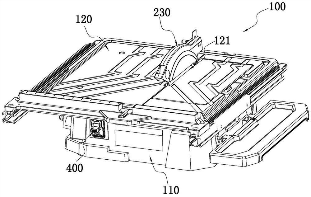
[0062] like figure 1As shown, it is a cutting tool 100 of the present invention, and the cutting tool 100 is a tile cutting machine, which can be used for cutting tiles, marble, granite and the like. The cutting tool 100 includes a base 110, an operating table 120 and a cutting mechanism.

[0063] like Figure 1-Figure 2 As shown, the cutting tool 100 further includes a switch assembly 400 and a control assembly (not shown in the figure), wherein the control assembly is used to control the operation of the cutting tool 100, and the switch assembly 400 is respectively connected with the driving member 210 and the control assembly to control the driving 210 start and stop.

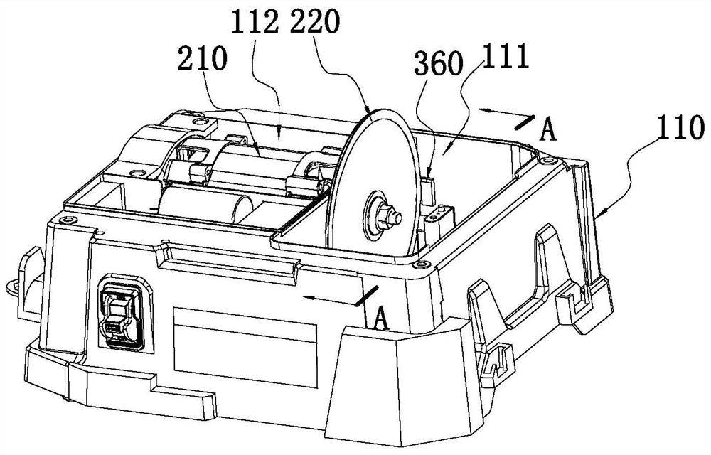
[0064] The base 110 can be placed on the bottom surface or other workbenches, such as figure 2 As shown, the base 110 is provided with an installation chamber 112 and a fluid chamber 111, wherein the fluid chamber 111 is used to hold the cooling liquid, and the bottom of the fluid chamber 111 is provided...


PUM


Abstract

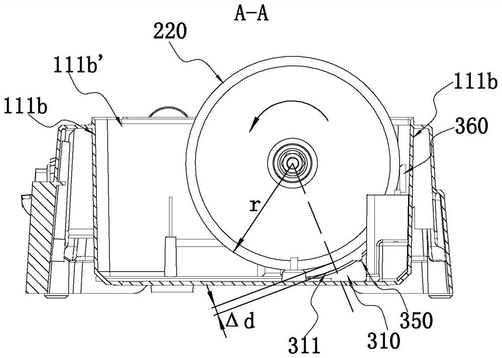
The invention discloses a cutting tool which comprises a base which comprises a fluid cavity for containing fluid; the operation table is arranged on the base; the cutting mechanism comprises a driving part and a cutting part, the driving part drives the cutting part to rotate around a first axis, and at least part of the cutting part protrudes and penetrates through the operation table; the cutting piece is provided with an entering area and a separating area on a rotating path of the cutting piece, the entering area refers to the rotating path where the cutting piece enters fluid and rotates to a lower limit position, and the separating area refers to the rotating path where the cutting piece rotates from the lower limit position to be separated from the fluid; the blocking mechanism is installed at the axial end of the cutting piece in the fluid cavity in the direction approximately perpendicular to the first axis; the blocking mechanism at least covers the cutting piece located in the separating area, the axial projection crosses the vertical center line of the cutting piece and extends towards the entering area, and the axial projection crosses the horizontal center line of the cutting piece and extends upwards.

Description

technical field [0001] The invention relates to an electric tool, in particular to a cutting tool. Background technique [0002] The traditional cutting tool includes a cutting piece that can cut the workpiece and a worktable. During the cutting process, the cutting piece will generate heat and become hot. The piece is partially immersed in the cooling liquid, during the cutting operation, the cutting piece rotates and the heat is carried away by the cooling liquid, [0003] During the use of the cutting tool 100 , due to the high-speed rotation of the cutting member 220 , the cooling liquid in the fluid chamber 111 is easily taken away, and the cooling liquid will be splashed by centrifugal force during the process of being driven away by the cutting member 220 . On the one hand, the splash of coolant will pollute the working environment, and the thrown coolant cannot be recovered, resulting in low efficiency of coolant use, and frequent addition of coolant is not conduciv...

Claims


Application Information

Patent Timeline
Patent Type & Authority Applications(China)
IPC IPC(8): B23D59/02
CPCB23D59/02
Inventor 陈智丰潘华平张长宁
Owner NANJING CHERVON IND
Learn More