Force-adjustable horizontal fixture for machining turbine blade
A steam turbine blade, horizontal technology, applied in the direction of manufacturing tools, metal processing equipment, metal processing machinery parts, etc., can solve the problems of low production efficiency, use, deformation, etc.
- Summary
- Abstract
- Description
- Claims
- Application Information
AI Technical Summary
Problems solved by technology
Method used
Image
Examples
Embodiment 1
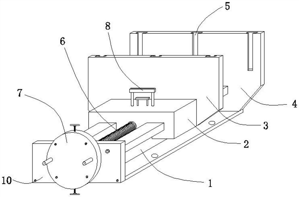
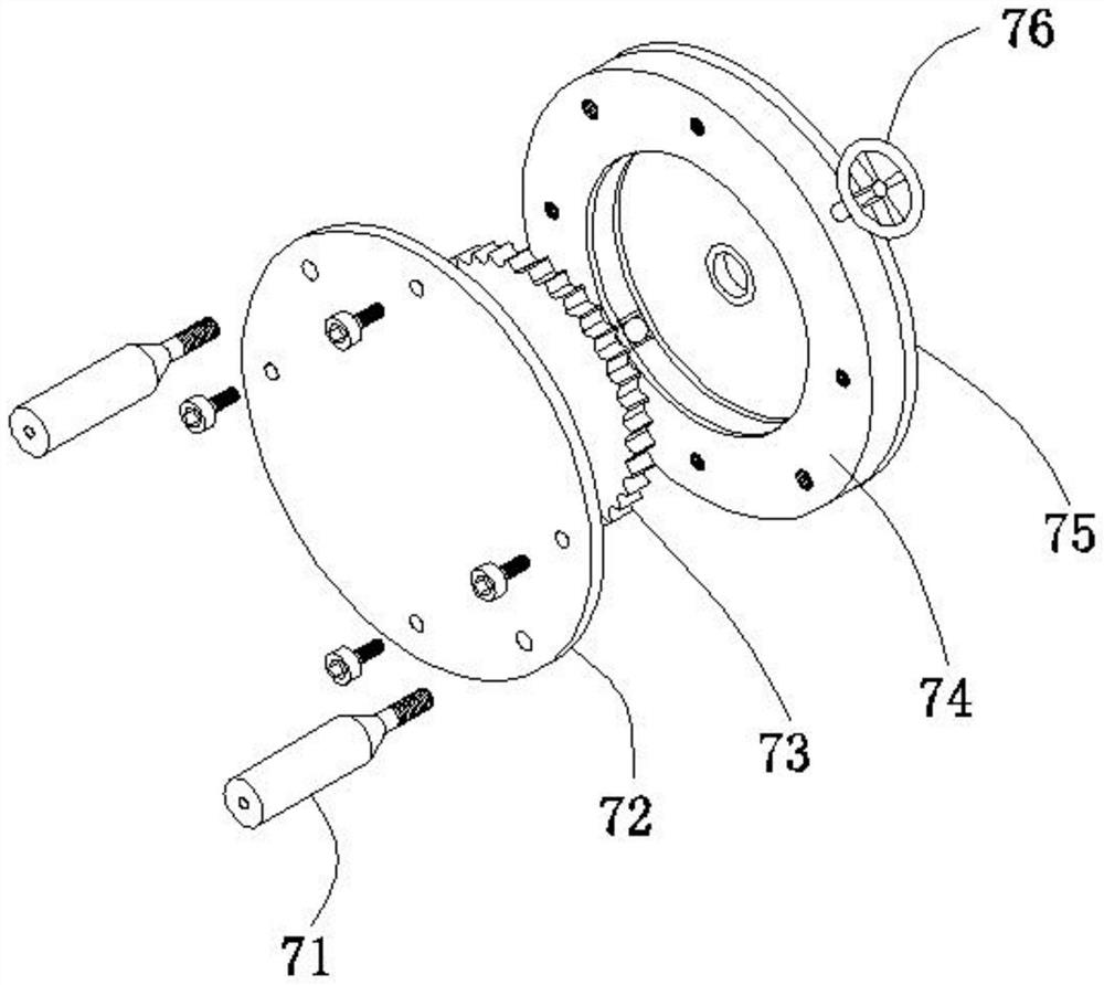
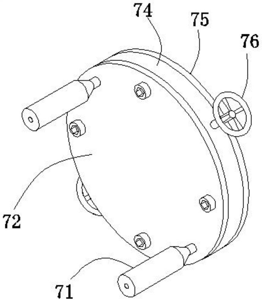
[0033] see Figure 1-6, this embodiment provides a horizontal jig for processing steam turbine blades with adjustable strength, including a mounting frame 1, one end of the mounting frame 1 is fixedly connected with a mounting plate 10, and the other end of the mounting frame 1 is fixedly connected with a fixing plate 4, which is fixed The plate 4 is fixedly connected with the mounting frame 1 by screws, so as to facilitate the maintenance and replacement of the sliding clamps in the mounting frame 1. A sliding block 2 is slidably installed in the middle of the mounting frame 1, and the sliding block 2 is close to the side of the fixed plate 4 The movable plate 3 is fixedly connected. By setting the movable plate 3 and the fixed plate 4, the steam turbine blades can be fixedly clamped. The inside of the sliding block 2 is rotatably installed with a lead screw 6, and one end of the lead screw 6 is rotatably connected to the fixed plate 4. , the other end of the screw rod 6 pene...
Embodiment 2
[0039] see Figure 1-10 , made further improvements on the basis of Example 1:
[0040] When the blade is integrally processed, it needs to be installed or removed on different processing fixtures many times. When adjusting the distance between the fixture heads, the existing fixture needs to rotate the adjusting rod at the tail, which makes the adjustment very inconvenient and cannot be quickly adjusted. The position of the fixture head is positioned according to the needs, which will affect the processing efficiency. In order to solve this problem, please refer to Figure 7 , a position adjusting device 8 is arranged in the inner cavity of the sliding block 2, please refer to Figure 8 , the position adjustment device 8 includes an upper clamping block 84 and a lower clamping block 86. By setting the upper clamping block 84 and the lower clamping block 86, the upper and lower clamping blocks can be separated during adjustment, and then the clamp head can be separated from t...
Embodiment 3
[0044] see Figure 1-13 , made further improvements on the basis of Example 2:
[0045] Most of the fixture heads of the existing clamping devices are made of hard materials. When clamping a curved workpiece, it is easy to cause deformation of the workpiece or damage to the workpiece. In order to prevent the clamp from causing damage to the steam turbine blade clamping, please refer to figure 1 , the opposite side of the moving plate 3 and the fixed plate 4 is provided with a connecting groove 5. By setting the connecting groove 5, the clamping head protection device can be adjusted according to different clamping workpieces, which effectively improves the use range of the fixture. Please see figure 1 and 11 , the movable plate 3 and the fixed plate 4 are movably installed with the flexible clamping device 9 through the connection slot 5 and the connection block 51, please refer to Figure 12-13 The flexible clamping device 9 includes an ejector pin storage box 91, a number...
PUM
 Abstract
Description
Claims
Application Information
 - R&D
- Intellectual Property
- Life Sciences
- Materials
- Tech Scout
- Unparalleled Data Quality
- Higher Quality Content
- 60% Fewer Hallucinations
Browse by: Latest US Patents, China's latest patents, Technical Efficacy Thesaurus, Application Domain, Technology Topic, Popular Technical Reports.
© 2025 PatSnap. All rights reserved.Legal|Privacy policy|Modern Slavery Act Transparency Statement|Sitemap|About US| Contact US: help@patsnap.com


