
Assembly method of joint module and joint robot

An assembly method and module technology, applied in the direction of manipulators, manufacturing tools, joints, etc.

Pending Publication Date: 2022-06-24
深圳市零差云控科技有限公司
View PDF0 Cites 0 Cited by
  • Summary
  • Abstract
  • Description
  • Claims
  • Application Information

AI Technical Summary

Problems solved by technology

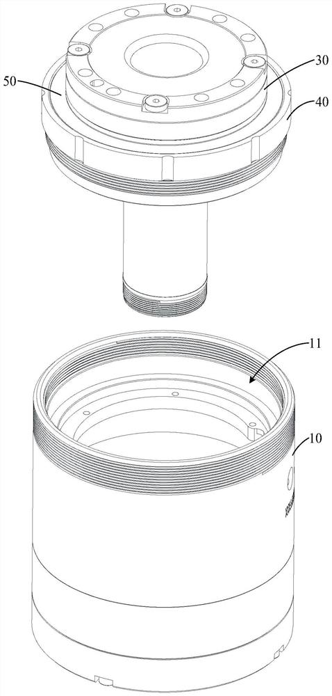
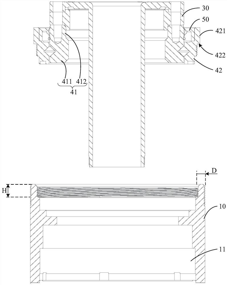
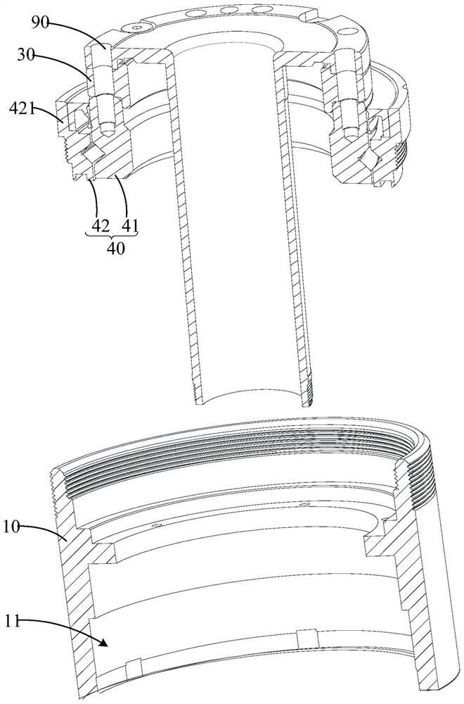
[0004] The main purpose of the present invention is to propose an assembly method of a joint module, aiming at solving the technical problem of how to improve the transmission accuracy of the joint module

Method used


Image

  • Assembly method of joint module and joint robot
  • Assembly method of joint module and joint robot
  • Assembly method of joint module and joint robot

Examples


Embodiment Construction

[0068] The technical solutions in the embodiments of the present invention will be clearly and completely described below with reference to the accompanying drawings in the embodiments of the present invention. Obviously, the described embodiments are only a part of the embodiments of the present invention, but not all of the embodiments. Based on the embodiments of the present invention, all other embodiments obtained by those of ordinary skill in the art without creative efforts shall fall within the protection scope of the present invention.

[0069] It should be noted that if there are directional indications (such as up, down, left, right, front, back, etc.) involved in the embodiments of the present invention, the directional indications are only used to explain a certain posture (as shown in the accompanying drawings). If the specific posture changes, the directional indication also changes accordingly.

[0070] In addition, if there are descriptions involving "first", ...


PUM


Abstract

The invention discloses a joint module assembly method and a joint robot, and the joint module comprises a motor assembly which comprises a shell, a motor stator and a motor rotor, and the shell is provided with a mounting cavity with an opening in one end; the speed reducer is mounted at the open end of the motor assembly; the supporting bearing comprises an inner ring and an outer ring which are rotationally matched, and the outer ring is fixedly matched with the opening end of the shell through threads; the speed reducer further comprises a flexible bearing and a flexible transmission wheel. One end of the flexible transmission wheel extends into the mounting cavity and is folded outwards in the radial direction to form an outer flange. A supporting step is arranged in the mounting cavity and abuts against the outer flanging. The assembly method of the joint module comprises the steps that the current pressure between the supporting step and the turned-over edge is obtained; comparing the current pressure with a preset pressure range; and determining that the current pressure exceeds a preset pressure range, and adjusting the axial relative position of the outer ring and the shell so as to enable the current pressure between the supporting step and the outer flange to be within the preset pressure range. According to the joint module, the transmission reliability of the joint module can be improved.

Description

technical field [0001] The invention relates to the technical field of driving equipment, in particular to an assembling method of a joint module and a joint robot. Background technique [0002] With the rapid development of industrial automation technology, robots, as an important industrial automation equipment, have been paid more and more attention and are more and more widely used. In robotics-related technologies, the control of moving parts such as robot joints is the most important and critical. [0003] In the related art robot joint module, the casing of the motor assembly and the reducer are usually connected by fasteners, so that the axial position between the casing and the reducer is fixed. In some solutions, the pressing force of the housing on the reducer will affect the transmission accuracy of the reducer. Since the axial position between the current casing and the reducer is not adjustable, the pressing force of the casing on the reducer cannot be adjust...

Claims


Application Information

Patent Timeline
Patent Type & Authority Applications(China)
IPC IPC(8): B25J19/00B25J17/00B25J17/02
CPCB25J19/007B25J17/00B25J17/02
Inventor 贾玺庆
Owner 深圳市零差云控科技有限公司
Learn More