
Automobile thermal management system and new energy automobile

A thermal management system and automotive technology, applied in the field of new energy vehicles, can solve the problems of blocking heat transfer between evaporator fins and air, reducing ride comfort, and affecting normal operation

Pending Publication Date: 2022-06-24
ZHEJIANG YINLUN MACHINERY
View PDF0 Cites 0 Cited by
  • Summary
  • Abstract
  • Description
  • Claims
  • Application Information

AI Technical Summary

Problems solved by technology

However, if the temperature of the refrigerant medium in the evaporator is too low, it is easy to cause the surface temperature of the evaporator to be too low. When the evaporator exchanges heat with the humid air, the moisture in the humid air will frost or freeze on the fins, blocking the fins of the evaporator. The contact heat exchange between the sheet and the air will affect the normal operation of the entire thermal management system, and if you want to defrost, you need to ensure that the temperature of the refrigerant flowing into the evaporator is relatively high, so that the heat released by the refrigerant at the condenser will be will decrease, affect the heating effect of the passenger compartment, and reduce the ride comfort

Method used


Image

  • Automobile thermal management system and new energy automobile
  • Automobile thermal management system and new energy automobile
  • Automobile thermal management system and new energy automobile

Examples


Embodiment Construction

[0025] In order to make the above objects, features and advantages of the present application more clearly understood, the specific embodiments of the present application will be described in detail below with reference to the accompanying drawings. In the following description, numerous specific details are set forth in order to provide a thorough understanding of the present application. However, the present application can be implemented in many other ways different from those described herein, and those skilled in the art can make similar improvements without departing from the connotation of the present application. Therefore, the present application is not limited by the specific embodiments disclosed below.

[0026] It should be noted that when a component is referred to as being "fixed to" or "disposed on" another component, it can be directly on the other component or there may also be an intervening component. When a component is considered to be "connected" to anoth...


PUM


Abstract

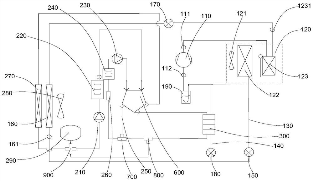
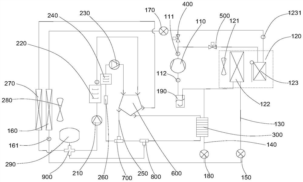
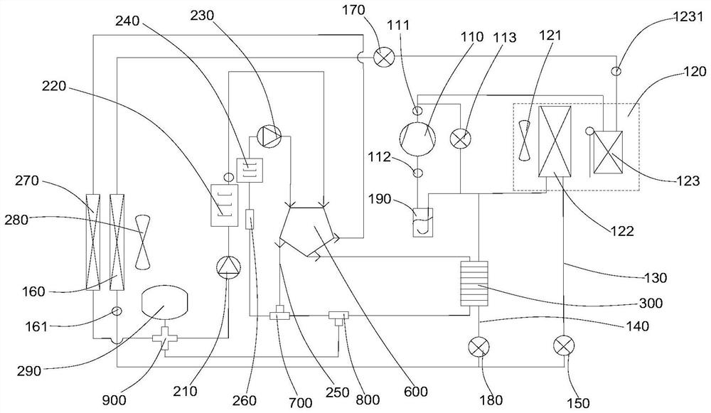
The invention relates to an automobile thermal management system which comprises a refrigerating medium loop, the refrigerating medium loop comprises a compressor, an air conditioner box, a first branch and a second branch, the air conditioner box comprises an evaporator and a condenser, an inlet of the condenser communicates with an outlet of the compressor, and an outlet of the condenser communicates with an inlet of the evaporator through the first branch. The first branch is communicated with an inlet of the compressor through a second branch, an outlet of the evaporator is communicated with the inlet of the compressor, and a first throttling piece is arranged on the first branch so as to control the flow of a refrigerating medium flowing into the evaporator and conduct throttling and pressure reduction on the refrigerating medium flowing into the evaporator. Two branches are arranged in the refrigerating medium loop, a high-temperature and high-pressure refrigerating medium flowing out of the compressor flows into the condenser and releases heat in the condenser, the refrigerating medium subjected to heat exchange is divided into two paths, one path flows into the evaporator through the first branch to lower the surface temperature of the evaporator, and the other path directly flows back to the compressor through the second branch to lower the surface temperature of the evaporator. And dehumidification at different temperatures is met through shunting.

Description

technical field [0001] The present application relates to the technical field of new energy vehicles, in particular to an automotive thermal management system and a new energy vehicle. Background technique [0002] The thermal management system is an important part of the new energy vehicle, which greatly affects the running performance of the vehicle and the user's comfort. The thermal management system includes a refrigerating medium circuit, and the refrigerating medium circuit at least includes a compressor and an air-conditioning box, and the air-conditioning box is provided with a condenser, an evaporator and a fan. In a low temperature environment, new energy vehicles have the need for heating and dehumidification. In the prior art, the high temperature and high pressure refrigerant flowing out of the compressor flows into the condenser, and releases heat to the passenger compartment under the action of the fan, so that the achieve heating. At the same time, the ref...

Claims


Application Information

Patent Timeline
IPC IPC(8): B60H1/00B60H1/22B60H1/32
CPCB60H1/00021B60H1/00321B60H1/00385B60H1/22B60H1/3204B60H1/3227B60H1/3228B60H1/32284B60H1/3229B60H1/00392B60H2001/00114B60H2001/2268B60H2001/2271B60H2001/3286
Inventor 孟娟杨云陈杰赵雷兴
Owner ZHEJIANG YINLUN MACHINERY
Learn More