Electric diaphragm pump

A diaphragm pump and diaphragm technology, applied in pumps, pump components, machines/engines, etc., can solve problems affecting the strength of components, and achieve the effects of reliable connection strength, saving material consumption, and simple structure

Pending Publication Date: 2022-06-24
ZHEJIANG SANHUA INTELLIGENT CONTROLS CO LTD
View PDF4 Cites 2 Cited by
  • Summary
  • Abstract
  • Description
  • Claims
  • Application Information

AI Technical Summary

Problems solved by technology

A typical electric diaphragm pump, the lower part of the pump body is directly sleeved on the outer periphery of the motor, and the upper part of the pump body and the pump cover are fastened through the protrusion to realize locking and fixing between the components; obviously, due to its own structural limitations, this scheme The non-peripheral pump body and the pump cover are fastened and locked, which directly affects the strength of the components in the use state that needs to be under pressure

Method used


Image

  • Electric diaphragm pump
  • Electric diaphragm pump
  • Electric diaphragm pump

Examples


Embodiment Construction

[0032] In order to make those skilled in the art better understand the technical solutions of the present invention, the present invention will be further described in detail below with reference to the accompanying drawings and specific embodiments.

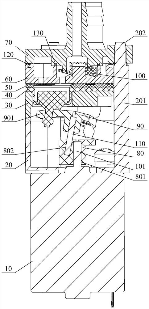
[0033] Without loss of generality, this implementation is based on figure 1 The electric diaphragm pump with three groups of piston chambers and water inlets, and one group of water outlet chambers and water outlets shown in the figure is used as a description body to describe this scheme in detail. It should be understood that the specific number of the water inlet and outlet channels does not constitute a substantial limit to the technical solution claimed in the present application.

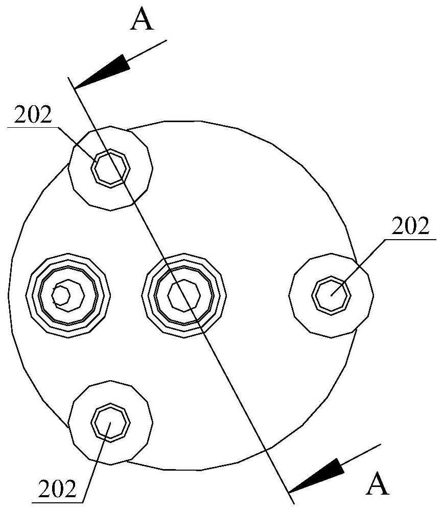
[0034] See figure 1 and figure 2 ,in, figure 1 A schematic diagram of the overall structure of the electric diaphragm pump according to this embodiment, the figure is figure 2 The diagram formed by the A-A section of , figure 2 This is a...


PUM


Abstract

An eccentric wheel and a driving body which are in deflection transmission connection are arranged in a pump body of the electric diaphragm pump, the eccentric wheel is connected with an output shaft of a motor, the driving body is connected with a main diaphragm, and an outlet one-way valve diaphragm is arranged between a pump cover and a diaphragm cover; wherein in the pump body, the diaphragm frame, the main diaphragm diaphragm, the inlet one-way valve diaphragm, the diaphragm cover and the pump cover which are stacked in sequence, the outer edge part of one member is provided with a plurality of mounting columns which are uniformly distributed in the circumferential direction and axially extend; the outer edge parts of other components are respectively and correspondingly provided with axially-through mounting parts for inserting the mounting columns, and are configured as follows: the mounting columns and the mounting parts form a circumferential limiting pair, and the end parts, extending out of the pump cover and/or the pump body, of the outwards-extending ends of the mounting columns are provided with locking parts; and the locking part is welded and fixed with the pump cover and/or the pump body. And the bearing strength of the component is effectively improved through structural optimization.

Description

technical field [0001] The invention relates to the technical field of fluid transportation, in particular to an electric diaphragm pump. Background technique [0002] Due to its compact structure, small size and light weight, diaphragm pumps are widely used in many fluid transportation fields, especially in beverage equipment such as water dispensers and coffee machines. A typical electric diaphragm pump, the lower part of the pump body is directly sleeved on the outer periphery of the motor, and the upper part of the pump body and the pump cover are fastened by the protrusions to achieve locking and fixing between the components; obviously, limited by its own structure, this solution The non-circumferential pump body and the pump cover are buckled and locked, which directly affects the strength of the components in the use state that requires pressure. SUMMARY OF THE INVENTION [0003] In order to solve the above technical problems, the present invention provides an ele...

Claims


Application Information

Patent Timeline
Patent Type & Authority Applications(China)
IPC IPC(8): F04B43/04F04B53/00F04B53/10F04B53/16
CPCF04B43/04F04B53/00F04B53/10F04B53/16
Inventor 不公告发明人
Owner ZHEJIANG SANHUA INTELLIGENT CONTROLS CO LTD
Why Eureka
Try Eureka