
Hydraulic oil temperature control structure of high-pressure diaphragm compressor

A high-pressure diaphragm and temperature control technology, which is applied in the direction of mechanical equipment, machines/engines, and liquid variable displacement machines, can solve problems such as increasing machine failure rates, reducing piston ring life, and reducing hydraulic oil leakage, so as to achieve avoidance. The effect of increasing consumption, prolonging life and improving efficiency

Active Publication Date: 2022-06-24
XI AN JIAOTONG UNIV
View PDF4 Cites 0 Cited by
  • Summary
  • Abstract
  • Description
  • Claims
  • Application Information

AI Technical Summary

Problems solved by technology

The suitable working temperature range of hydraulic oil is 20-60°C. Long-term exposure to high temperature environment will accelerate the aging of hydraulic oil, reduce the viscosity of hydraulic oil and increase the leakage, and long-term exposure to low temperature environment will increase the viscosity of hydraulic oil, resulting in diaphragm compressor failure. increase in energy consumption
At the same time, if the piston is in high temperature hydraulic oil for a long time, it will also accelerate the aging of the piston ring, reduce the life of the piston ring, and increase the failure rate of the machine

Method used


Image

  • Hydraulic oil temperature control structure of high-pressure diaphragm compressor
  • Hydraulic oil temperature control structure of high-pressure diaphragm compressor
  • Hydraulic oil temperature control structure of high-pressure diaphragm compressor

Examples


Embodiment Construction

[0027] The technical solutions in the embodiments of the present application will be clearly and completely described below with reference to the drawings in the embodiments of the present application. Obviously, the described embodiments are only a part of the embodiments of the present application, but not all of the embodiments. Based on the embodiments in the present application, all other embodiments obtained by those of ordinary skill in the art without creative efforts shall fall within the protection scope of the present application.

[0028] In the description of this application, it should be understood that the terms "center", "upper", "lower", "front", "rear", "left", "right", "vertical", "horizontal", The orientation or positional relationship indicated by "top", "bottom", "inner", "outer", etc. is based on the orientation or positional relationship shown in the drawings, and is only for the convenience of describing the present application and simplifying the desc...


PUM


Abstract

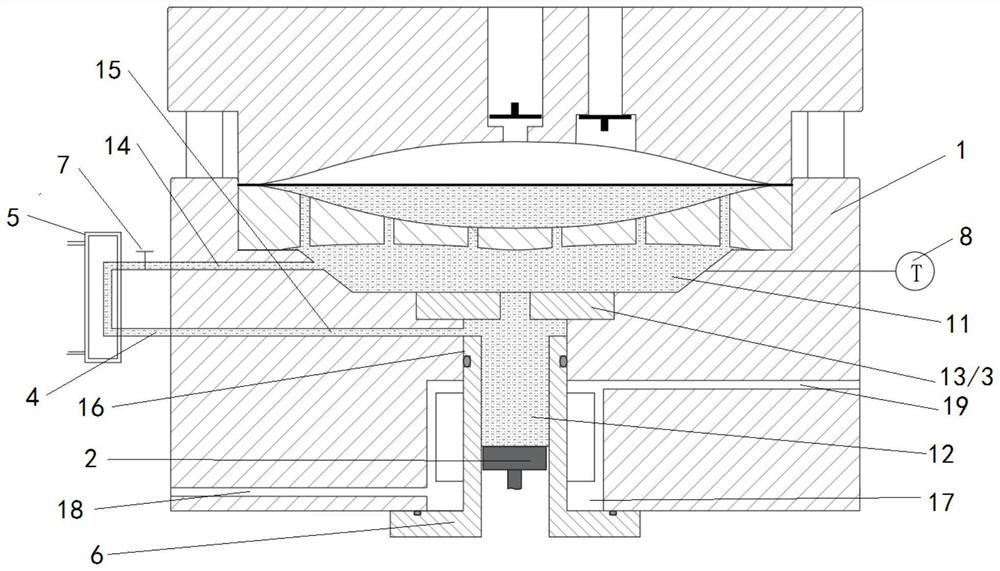
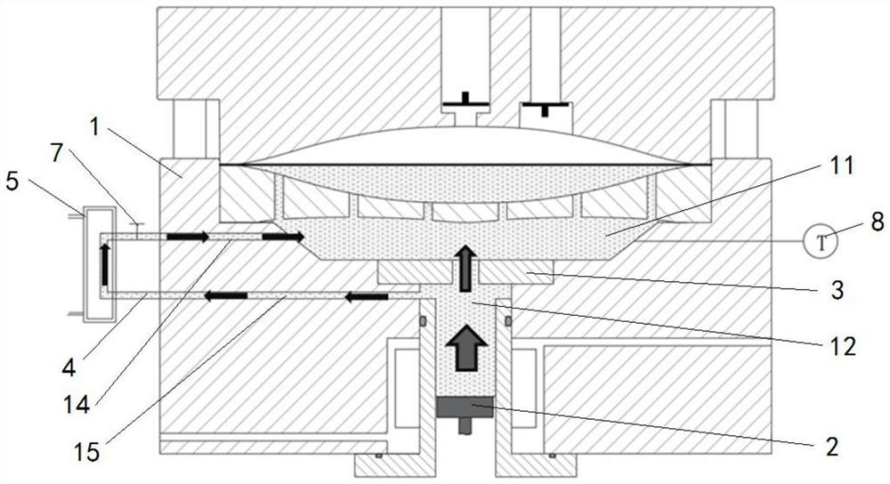
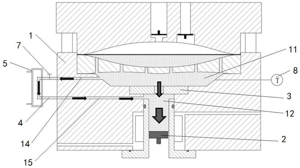
The invention discloses a hydraulic oil temperature control structure of a high-pressure diaphragm compressor, and relates to the technical field of diaphragm compressors. The temperature of the hydraulic oil is accurately controlled by dynamically adjusting heat exchange between the hydraulic oil and the outside, energy consumption increase caused by too low oil temperature can be avoided, hydraulic oil emulsification caused by too high oil temperature can be prevented, the efficiency of the high-pressure diaphragm compressor is improved, and the service life of the high-pressure diaphragm compressor is prolonged. The hydraulic oil temperature control structure of the high-pressure diaphragm compressor comprises an oil side diaphragm head, an oil cavity and an oil cylinder hole which are communicated with each other are formed in the oil side membrane head; a piston is arranged in the oil cylinder hole and can reciprocate in the oil cylinder hole; a mounting cavity is formed between the oil cavity and the oil cylinder hole, and an oil distributor is arranged in the mounting cavity; an external oil pipe is arranged on the outer side of the oil side membrane head; two ends of the external oil pipe are respectively communicated with the oil cavity and the oil cylinder hole; and an enhanced heat exchange device is arranged outside the external oil pipe. The performance and reliability of the high-pressure diaphragm compressor are improved.

Description

technical field [0001] The present application relates to the technical field of diaphragm compressors, and in particular, to a temperature control structure for hydraulic oil of a high-pressure diaphragm compressor. Background technique [0002] Diaphragm compressors rely on the piston to push the hydraulic oil and then drive the diaphragm to flex and deform to compress the gas. When diaphragm compressors are used in high-pressure environments such as hydrogen refueling stations, the pressure of hydraulic oil will generally reach 100MPa or even higher. The hydraulic oil in the diaphragm compressor is difficult to ensure that it is pure, and generally some tiny air bubbles are mixed in, and the gas itself has a certain solubility in the hydraulic oil. The hydraulic oil mixed with gas will generate a certain amount of heat during the compression process, and in order to ensure the strength and rigidity of the compressor structure, the wall thickness of the oil cavity of the ...

Claims


Application Information

Patent Timeline
Patent Type & Authority Applications(China)
IPC IPC(8): F04B45/053F04B39/06F04B39/12
CPCF04B45/0533F04B39/06F04B39/126F04B39/122
Inventor 贾晓晗任省栋石张平彭学院
Owner XI AN JIAOTONG UNIV
Learn More