Cloud cover state observation system

A state observation and cloud cover technology, applied in the direction of measuring devices, instruments, scientific instruments, etc., can solve problems such as insufficient integration, image interference, and lack of effective protection of imaging modules, and achieve automatic protection, real imaging, and rich details Effect

Pending Publication Date: 2022-06-24
CHANGCHUN INST OF OPTICS FINE MECHANICS & PHYSICS CHINESE ACAD OF SCI
View PDF0 Cites 0 Cited by
  • Summary
  • Abstract
  • Description
  • Claims
  • Application Information

AI Technical Summary

Problems solved by technology

[0003] At present, the cloud amount observation equipment on the market is mainly divided into two categories: cloud amount observation equipment in the visible light band and cloud amount observation equipment in the infrared band. Large impact, the image is easily disturbed by the outside world
For the infrared band cloud amount observation equipment, the infrared band detector is less affected by the brightness of the skylight background. Regardless of the brightness of the external environment, it can obtain a clear image of the cloud layer and can observe the state of the cloud layer all day long. Imaging effect and details are not as good as visible light detectors
As a result, a cloud cover observation system integrated with cloud cover observation equipment in the visible light band and infrared band cloud cover observation equipment emerged as the times require, but the existing cloud cover observation system is not integrated enough, lacks a leveling structure and lacks an effective imaging module. Protect

Method used


Image

  • Cloud cover state observation system
  • Cloud cover state observation system
  • Cloud cover state observation system

Examples


Embodiment Construction

[0026] Hereinafter, embodiments of the present invention will be described with reference to the accompanying drawings. In the following description, the same modules are denoted by the same reference numerals. In the case of the same reference numerals, their names and functions are also the same. Therefore, its detailed description will not be repeated.

[0027] In order to make the objectives, technical solutions and advantages of the present invention clearer, the present invention will be further described in detail below with reference to the accompanying drawings and specific embodiments. It should be understood that the specific embodiments described herein are only used to explain the present invention, but not to limit the present invention.

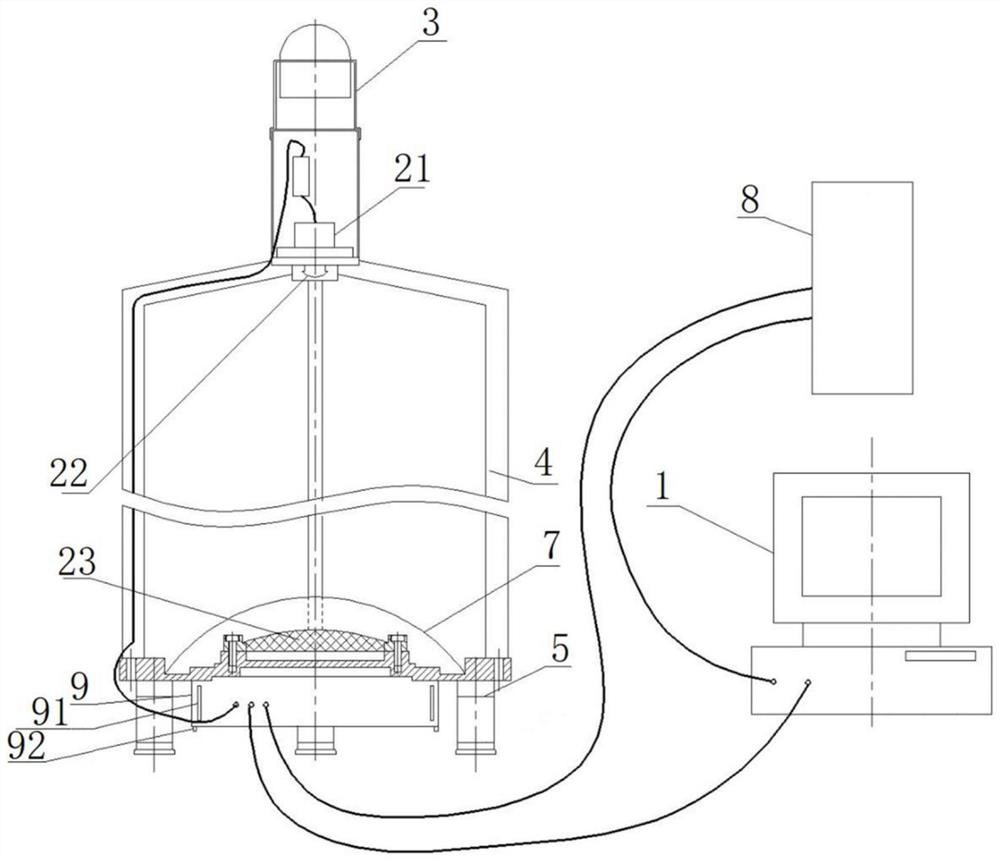
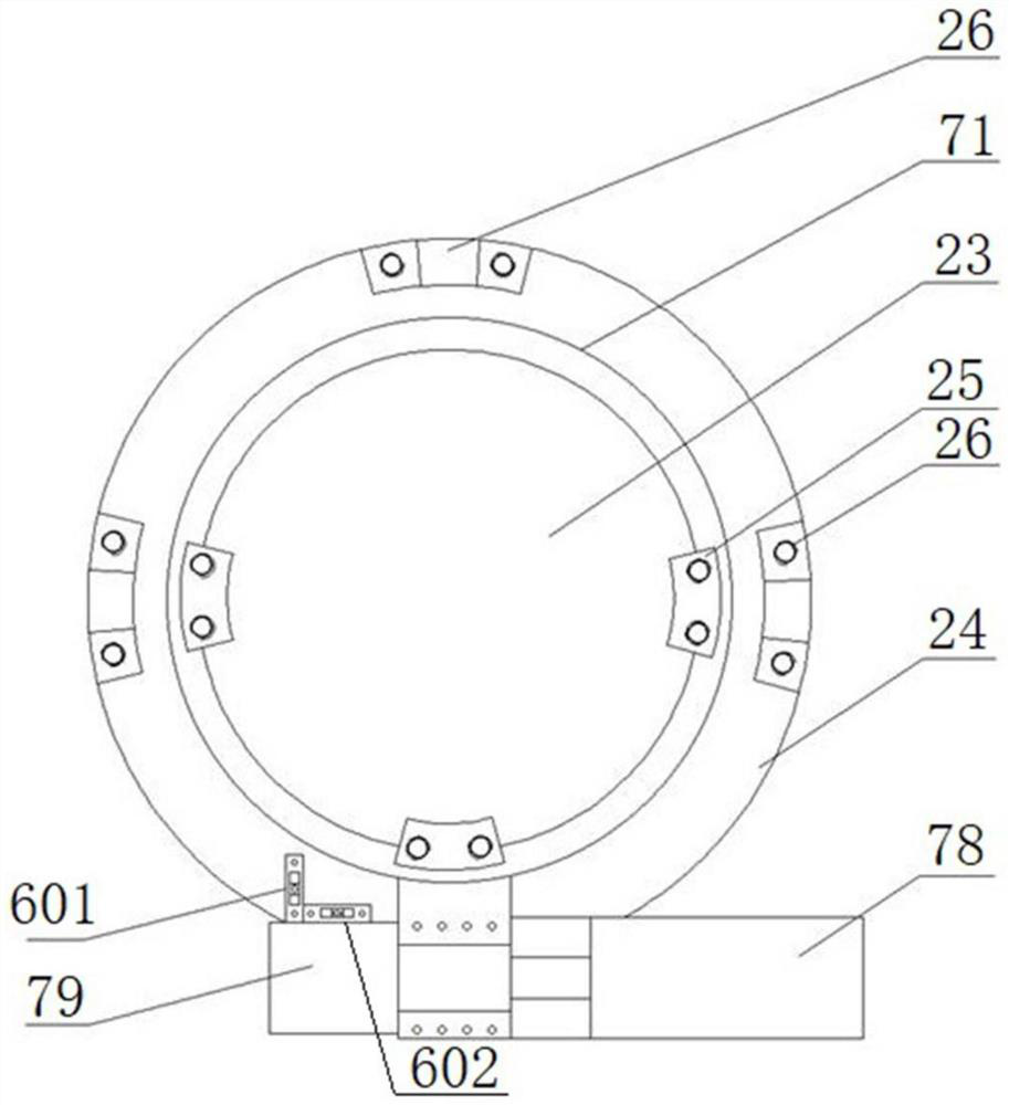
[0028] figure 1 and figure 2 The overall structure and partial top-view structure of the cloud cover state observation system provided according to the embodiment of the present invention are respectively shown.

[0029] ...


PUM


Abstract

A cloud cover state observation system provided by the present invention comprises a cloud cover instrument and a data processing terminal, the cloud cover instrument comprises a visible light wave band imaging module, an infrared wave band imaging module, a support frame and an image transmission module, the infrared wave band imaging module comprises an infrared wave band detector, a lens group, a reflection light collecting mirror and a mirror seat, the reflection light collecting mirror is fixed on the mirror seat, and the infrared wave band detector is fixed on the support frame. The lens group and the infrared band detector are sequentially arranged in the reflection direction of the reflection light collecting mirror, and the infrared band imaging module is used for collecting an infrared band cloud cover picture; the visible light wave band imaging module is fixed above the infrared wave band detector and is used for acquiring a visible light wave band cloud cover picture; the image transmission module is used for transmitting the visible light wave band cloud cover image and the infrared wave band cloud cover image to the data processing terminal for image fusion. According to the invention, the two detectors cooperate with each other for observation, all-day cloud cover observation can be realized, the observation condition is not influenced by factors such as the sky background, the observation field of view is large, and the resolution is high.

Description

technical field [0001] The invention relates to the technical field of meteorological observation, in particular to a cloud state observation system. Background technique [0002] Cloud cover observation can be widely used in meteorology, scientific research, astronomy, military and other fields, and is an important way to obtain cloud information in the middle and low altitudes. The cloud cover observation equipment provides cloud meteorological warning information to the outside by observing the changes of cloud state, assisting and optimizing the observation and scheduling of telescopes. [0003] At present, the cloud cover observation equipment on the market is mainly divided into two categories: the visible light band cloud cover observation equipment and the infrared wave band cloud cover observation equipment. For the visible light band cloud cover observation equipment, the visible light band detector has real imaging and rich details, but it is affected by external ...

Claims


Application Information

Patent Timeline
IPC IPC(8): G01N21/84G01N21/01G01W1/00
CPCG01N21/84G01N21/01G01W1/00Y02A90/10
Inventor 王昊京王建立王志王超
Owner CHANGCHUN INST OF OPTICS FINE MECHANICS & PHYSICS CHINESE ACAD OF SCI
Why Eureka
Try Eureka