Cleaning device for forging die
A technology for cleaning devices and molds, applied in the field of forging molds, to achieve the effect of efficient flushing
- Summary
- Abstract
- Description
- Claims
- Application Information
AI Technical Summary
Problems solved by technology
Method used
Image
Examples
Embodiment 1
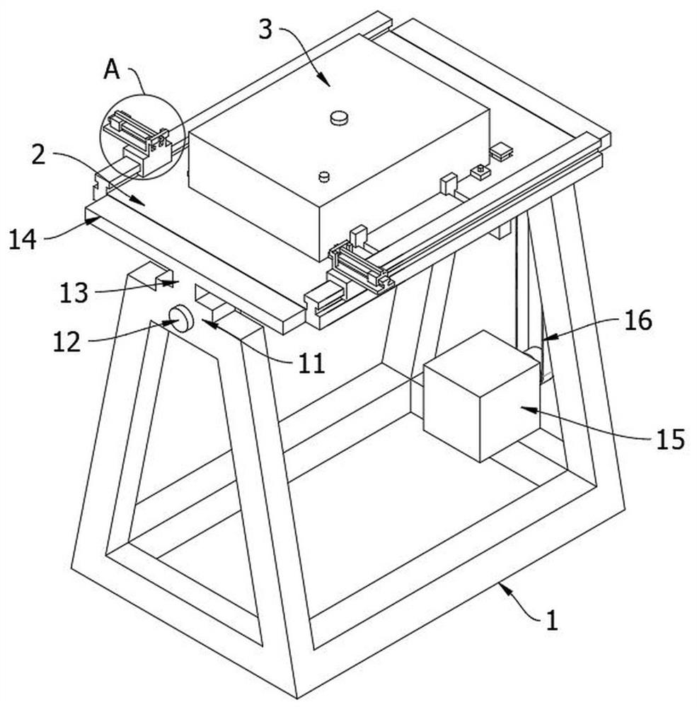
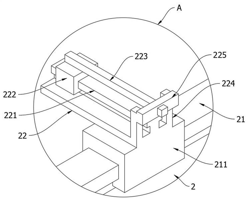
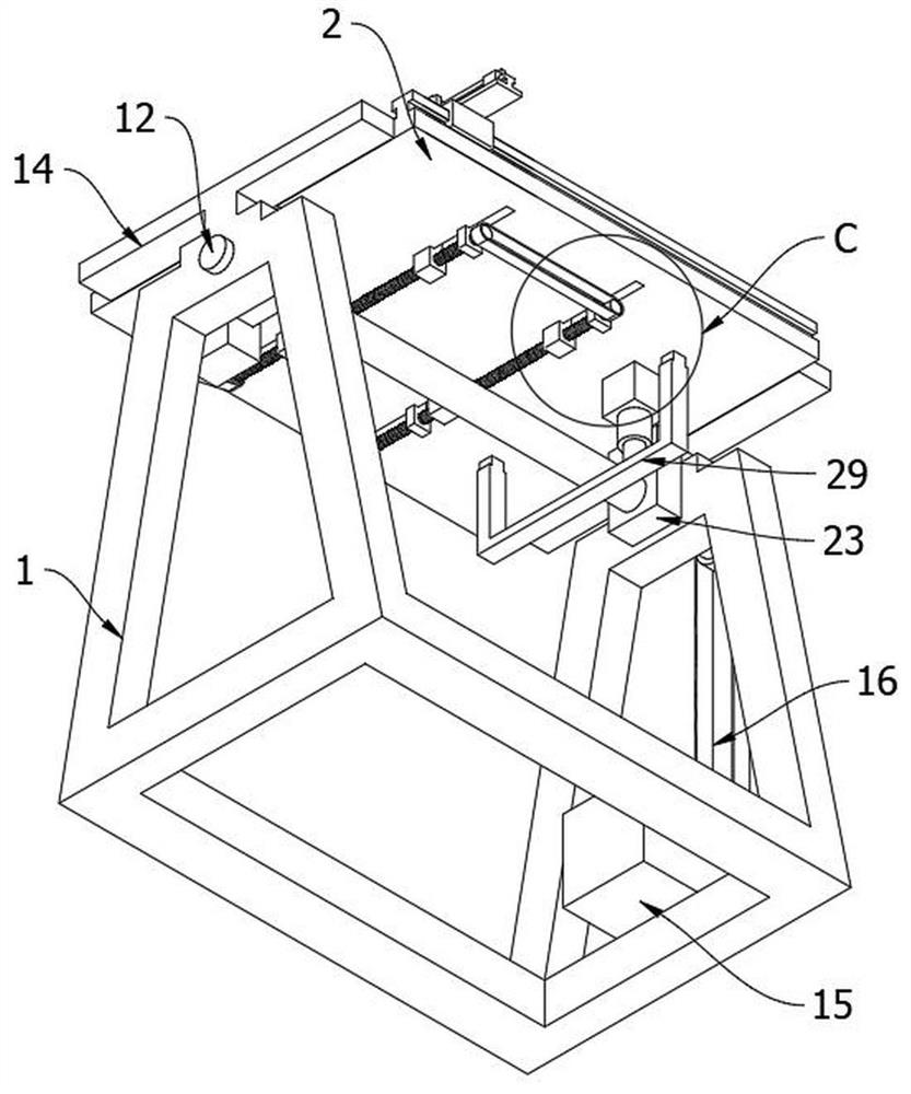
[0044] like Figure 1-10 A cleaning device for a forging die, comprising an overturning table, the overturning table comprising a rack A1 and a table top 2 that can be flipped over and arranged on the rack A1; The cleaning and fixing cover 3; the cleaning and fixing cover 3 includes a cover body 31, a sealing ridge 32 arranged on the inner top side of the cover body 31 and abutting on the surface of the mold during installation, and a cavity structure 33 is provided on the top of the cover body 31 , a plurality of threaded holes 35 communicating with the cavity structure 33 are arranged on the inner side of the sealing convex edge 32, and the threaded holes 35 are equipped with cleaning nozzles; The outer side of the cover body 31 is also provided with a fluid outlet pipe 39 penetrating the top of the cover body 31; a mounting block 36 is provided on the peripheral side of the open end of the cover body 31, a positioning sleeve 361 is provided on one side of the mounting block...
Embodiment 2
[0050] Embodiment 2, on the basis of embodiment 1, as Figure 11-13 ; Be positioned at one side of the overturning table and also be provided with a conveying mechanism for draining the cleaned mould, the conveying mechanism comprises a frame B4, the first conveying roller 41 is provided on the frame B4, and the end of the frame B4 is provided with a reversed rectangle Frame A42, the rectangular frame A42 is provided with a second conveying roller 43, the two ends of the upper surface of the rectangular frame A42 are respectively provided with an inverted U-shaped protective frame A44 and a U-shaped protective frame B45, and the U-shaped protective frame B45 is provided with a material stopper Plate 46; both sides of the rectangular frame A42 are provided with rotating columns rotatably installed on the frame B4, the end of a rotating column penetrates the frame B4 and is connected to the motor C41 through the transmission chain D48; the end of the frame B4 is provided with Fr...
Embodiment 3
[0053] Embodiment 3, on the basis of implementing 1 or 2, as Figure 14-15 A cooling mechanism for cooling the mould is also provided on one side of the turning table, the cooling mechanism includes a rack E7, the rack E7 is provided with a fifth conveying roller 71, and the middle of the rack E7 is provided with a rectangular frame that moves up and down B86, a sixth conveying roller 87 is arranged in the rectangular frame B86; a cooling groove 200 is also arranged directly below the rectangular frame B86, a side post 8 is arranged on one side of the frame E7, and the side post 8 is provided with a sliding rail along the vertical direction D81, the sliding rail D81 is provided with an electric sliding block D82, and the electric sliding block D82 is provided with a Z-shaped connecting frame 83; the bottom side of the rectangular frame B86 is provided with two U-shaped connecting frames 85, and a U-shaped connecting frame 85 is connected between them. The connecting bar 84, th...
PUM
 Abstract
Description
Claims
Application Information
 - R&D
- Intellectual Property
- Life Sciences
- Materials
- Tech Scout
- Unparalleled Data Quality
- Higher Quality Content
- 60% Fewer Hallucinations
Browse by: Latest US Patents, China's latest patents, Technical Efficacy Thesaurus, Application Domain, Technology Topic, Popular Technical Reports.
© 2025 PatSnap. All rights reserved.Legal|Privacy policy|Modern Slavery Act Transparency Statement|Sitemap|About US| Contact US: help@patsnap.com


