Temperature detection method, device and system for magnetically levitated train and server

A technology for maglev trains and detection methods, which is applied in the direction of measuring devices, thermometers, thermometers, etc., can solve problems such as reducing debugging efficiency, collecting equipment design, routing design, vehicle weight control difficulty, and routing difficulties, etc., to improve Debugging efficiency and effect, avoiding the effect of vehicle wiring design and weight control

Pending Publication Date: 2022-06-28
CRRC QINGDAO SIFANG CO LTD
View PDF0 Cites 1 Cited by
  • Summary
  • Abstract
  • Description
  • Claims
  • Application Information

AI Technical Summary

Problems solved by technology

Among them, the method of presetting the sensor inside the electromagnet needs to pre-embed the temperature sensor into the electromagnet during the production of the electromagnet. The advantage is that the measured value is the closest to the real value. The disadvantage is that each pole of the electromagnet generates a temperature signal. Due to the huge number of electromagnets, it is extremely difficult for the design of the acquisition equipment, the design of the wiring and the control of the weight of the vehicle; in the contact measurement method, the patch temperature sensor method also faces the problem of wiring, and the advantages of using fiber grating sensors are One optical fiber can measure the temperature of multiple electromagnets, which reduces the requirements for acquisition equipment, wiring design and vehicle weight. However, since the optical fiber is deployed on the surface of the electromagnet, the frequent disassembly and assembly of the electromagnet during the debugging process will be more cumbersome , reducing the debugging efficiency

Method used


Image

  • Temperature detection method, device and system for magnetically levitated train and server
  • Temperature detection method, device and system for magnetically levitated train and server
  • Temperature detection method, device and system for magnetically levitated train and server

Examples


Embodiment Construction

[0051] In order to make the purposes, technical solutions and advantages of the embodiments of the present invention clearer, the technical solutions in the embodiments of the present invention will be clearly and completely described below with reference to the accompanying drawings in the embodiments of the present invention. Obviously, the described embodiments These are some embodiments of the present invention, but not all embodiments. Based on the embodiments of the present invention, all other embodiments obtained by those of ordinary skill in the art without creative efforts shall fall within the protection scope of the present invention.

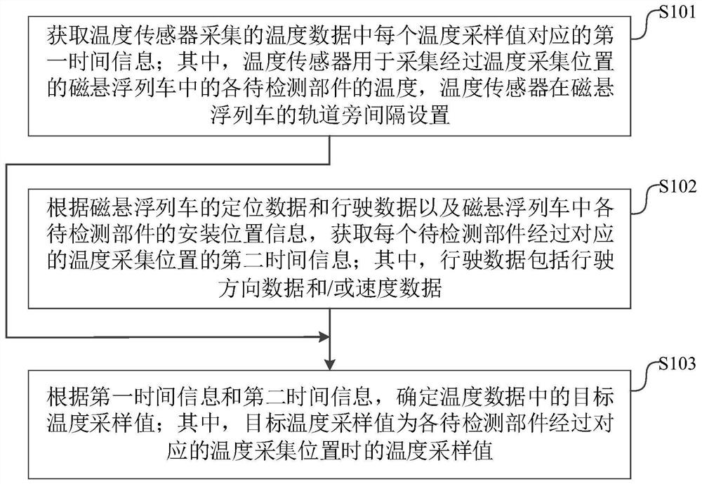
[0052] Please refer to figure 1 , figure 1 This is a flowchart of a temperature detection method for a maglev train provided by an embodiment of the present invention. The method can include:

[0053] Step 101: Obtain the first time information corresponding to each temperature sampling value in the temperature data collected by ...


PUM


Abstract

The invention discloses a temperature detection method, device and system for a maglev train and a server. The method comprises the steps that first time information corresponding to each temperature sampling value in temperature data collected by a temperature sensor is obtained; according to the positioning data and the driving data of the magnetically levitated train and the installation position information of each to-be-detected component in the magnetically levitated train, obtaining second time information of each to-be-detected component passing through the corresponding temperature acquisition position; determining a target temperature sampling value in the temperature data according to the first time information and the second time information; according to the invention, through comparative analysis of the time information of the temperature sampling value collected by the temperature sensor and the time information of the to-be-detected part passing through the temperature collection position, the accurate temperature value collected by the temperature sensor when the to-be-detected part passes through the temperature collection position is extracted; therefore, the temperature of the electromagnet of the maglev train can be accurately detected in a non-contact manner, and the influence on the wiring design and weight control of the train is avoided.

Description

technical field [0001] The invention relates to the technical field of maglev trains, in particular to a temperature detection method, device, system and server for a maglev train. Background technique [0002] At present, there are mainly two ways to monitor the electromagnet temperature of maglev trains (that is, maglev trains): 1) a preset sensor method inside the electromagnet; 2) a contact measurement method (such as a patch temperature sensor or fiber grating, etc.) ). Among them, the method of presetting the sensor inside the electromagnet requires that the temperature sensor be embedded in the electromagnet during the production of the electromagnet. The advantage is that the measured value is the closest to the real value. Due to the huge number of electromagnets, it is extremely difficult to design the acquisition equipment, wiring design and vehicle weight control; in the contact measurement method, the patch temperature sensor method also faces wiring problems, ...

Claims


Application Information

Patent Timeline
Patent Type & Authority Applications(China)
IPC IPC(8): G01K13/00
CPCG01K13/00
Inventor 刘先恺侯圣杰付善强齐江永李琪
Owner CRRC QINGDAO SIFANG CO LTD
Why Eureka
Try Eureka