Frame structure motor and assembling method

A frame structure and rear frame technology, which is applied in the field of frame structure motors and assembly, can solve the problems of multiple assembly processes, tedious and time-consuming repair and disassembly, and inability to repair and replace, so as to reduce production costs, maintain and upgrade economically and conveniently, The effect of increasing power

Pending Publication Date: 2022-06-28
大连智鼎科技有限公司
View PDF0 Cites 0 Cited by
  • Summary
  • Abstract
  • Description
  • Claims
  • Application Information

AI Technical Summary

Problems solved by technology

Therefore, this type of structure motor has problems such as many assembly processes, cumbersome and time-consuming repair and disassembly, and even if there is a problem with the stator coil or the power of the motor needs to be upgraded during the repair, it is still difficult because the stator winding and the base reel are cast as a whole. Cannot be repaired or replaced

Method used


Image

  • Frame structure motor and assembling method
  • Frame structure motor and assembling method
  • Frame structure motor and assembling method

Examples


Embodiment 1

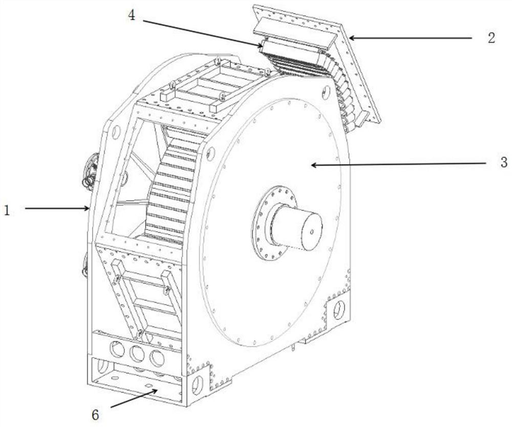
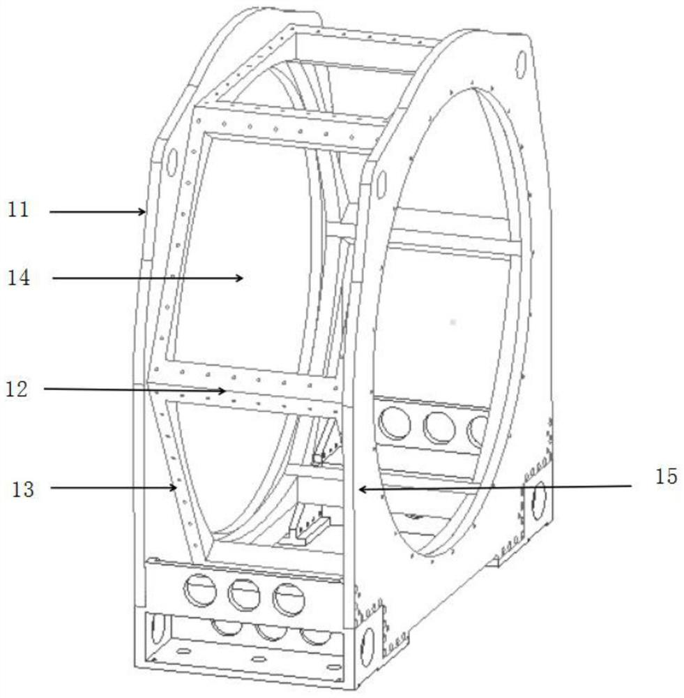
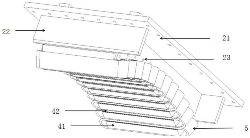
[0024] like Figure 1-3 As shown, this embodiment provides a frame structure motor, including a base casing, a stator casing and a modular stator, the base casing is provided with a rotor inside, the rotor is mounted on the motor shaft through a rotor bracket, and the rotor is mounted on the rotor. Magnetic steel is arranged between the punching pieces, and the present invention does not improve the rotor part. The base shell includes a front frame and a rear frame, a front cover mounting plate is fixed on the outside of the front frame, a rear cover mounting plate is fixed on the outside of the rear frame, and a plurality of lateral supports are welded between the front frame and the rear frame. The two adjacent transverse support beams and the side walls of the front and rear frames form a rectangular through slot, and a stator casing is assembled in the rectangular through slot, and the stator casing includes a stator mounting plate, a limit side plate, an arc An iron core...

Embodiment 2

[0031] This embodiment provides a method for assembling a frame structure motor, which is different from a traditional drum structure motor. The base is divided into two parts: a base shell and a stator casing. The stator part is not installed in the drum shell in the traditional way, but It is installed on the stator casing. Due to the lighter volume and structure of the stator casing, the stator processing method will also be simplified. The base shell and stator casing provided in Example 1 can realize the installation of the stator iron core from the outside to the main body of the motor, and the modular stator processing can be completed in parallel with the assembly of the whole machine, realizing the innovation of the assembly method. The specific implementation process is described below:

[0032] The base shell is used as an effective support for the stator core, and the stator casing can realize the modular stator installation; the modular stator is placed on the tool...


PUM


Abstract

The invention discloses a frame structure motor and an assembly method. The frame structure motor comprises a base shell, a stator shell and a modular stator, the base shell comprises a front frame and a rear frame, a front end cover mounting plate is fixed to the outer side of the front frame, a rear end cover mounting plate is fixed to the outer side of the rear frame, a plurality of transverse supporting beams are welded between the front frame and the rear frame, and a rectangular through groove is formed by every two adjacent transverse supporting beams and the side walls of the front frame and the rear frame. A rectangular through groove is formed in the stator shell, a stator shell is assembled in the rectangular through groove, the stator shell comprises a stator mounting plate, limiting side plates and an arc-shaped iron core mounting block, the arc-shaped iron core mounting block used for mounting a modular stator is fixed on the inner wall of the stator mounting plate, and the limiting side plates are arranged on the two sides of the arc-shaped iron core mounting block. According to the invention, tools and working hours can be saved, the reliability of the motor is improved, and each modular stator can be conveniently and rapidly disassembled and replaced under the condition that the whole machine is not disassembled.

Description

technical field [0001] The invention relates to the technical field of permanent magnet motors, in particular to a frame structure motor and an assembling method. Background technique [0002] Permanent magnet motor is mainly composed of base, end cover, bearing, stator core, stator winding, rotor core, permanent magnet, motor shaft and other components. At present, the structure of most permanent magnet motors is as follows: the main body of the base is a drum structure, the stator core is attached to the drum, and the stator core, stator winding, and drum are formed into a whole by casting, and then Install end caps and bearings to support the rotor part. [0003] Most of the above-mentioned types of motors are assembled with the stator installed first, and then the rotor; that is, the assembled stator core is first installed into the base drum, and the stator winding is embedded in the core slot, and all windings are wired. Carry out varnishing and pouring. At this time...

Claims


Application Information

Patent Timeline
Patent Type & Authority Applications(China)
IPC IPC(8): H02K5/04H02K3/28H02K3/12H02K3/48H02K3/52H02K15/00
CPCH02K5/04H02K3/28H02K3/12H02K3/48H02K3/522H02K15/00
Inventor 王永胜刘潇隋雪峰李景天
Owner 大连智鼎科技有限公司
Why Eureka
Try Eureka