Chest drainage nursing device for thoracic surgery department

A nursing device and thoracic surgery technology, applied in the direction of suction equipment, etc., can solve the problems of small application range of nursing devices, instability of artificially squeezed drainage tubes, etc., and achieve the effect of improving convenience, application range, and efficiency

Inactive Publication Date: 2022-07-01
CHONGQING UNIV CANCER HOSPITAL
View PDF0 Cites 1 Cited by
  • Summary
  • Abstract
  • Description
  • Claims
  • Application Information

AI Technical Summary

Problems solved by technology

[0005] Aiming at the deficiencies of the prior art, the present invention provides a chest drainage nursing device for thoracic surgery, which has the advantages of being able to adjust the height of the nursing device, automatically squeezing the drainage tube, ensuring the stability of extrusion, improving work efficiency, etc., and solving the problem of Solved the problem that the range of application of the nursing device is small, and the artificially squeezed drainage tube is unstable

Method used


Image

  • Chest drainage nursing device for thoracic surgery department
  • Chest drainage nursing device for thoracic surgery department
  • Chest drainage nursing device for thoracic surgery department

Examples


Embodiment 1

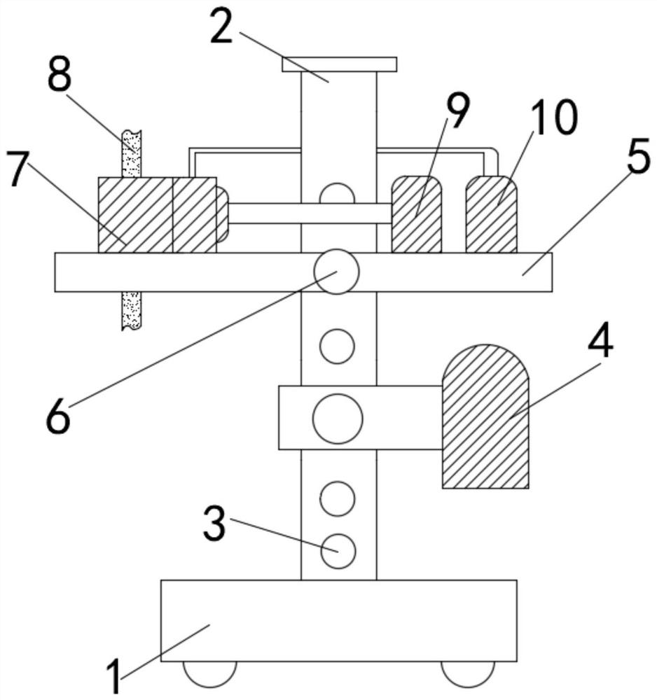
[0022] Example 1, as Figure 1-3 As shown in the figure, a chest drainage nursing device for thoracic surgery includes a base 1, a support rod 2 is fixedly connected to the middle position of the outer surface of the upper end of the base 1, and a slot 3 is opened on the outer surface of the front end of the support rod 2. A bracket 5 is slidably connected to the outer surface of the support rod 2 at a position close to the top, a drainage box 4 is slidably connected to the outer surface of the support rod 2 below the support rod 5, and a fixing bolt is rotatably connected to the middle position of the outer surface of the front end of the support rod 5. 6. A fixing block 7 is fixedly connected to the outer surface of the upper end of the bracket 5 near the left side, and a first hydraulic device 9 is fixedly connected to the outer surface of the upper end of the bracket 5 near the right side. The first hydraulic device The right side of the 9 is fixedly connected with the bra...

Embodiment 2

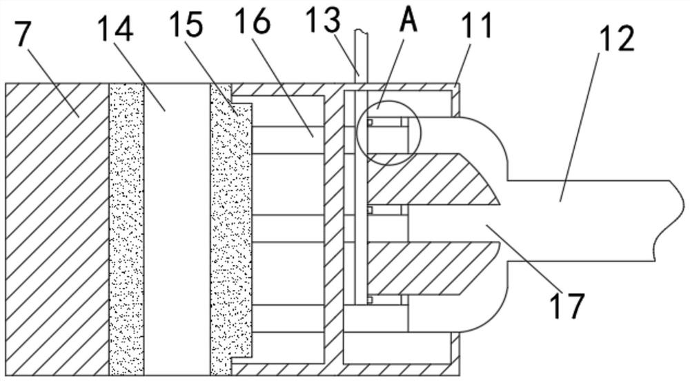
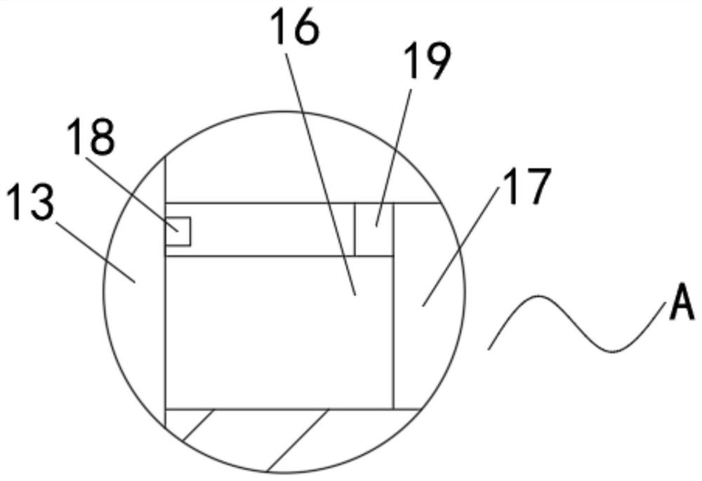
[0023] Example 2, as Figure 1-2 As shown in the figure, the right outer surface of the fixing block 7 is fixedly connected with an adjustment cabin 11, the right outer surface of the adjustment cabin 11 is fixedly connected with a distribution chamber 17, and a middle position of the upper outer surface of the fixing block 7 is opened. The fixing groove 14, the inner surface of the fixing groove 14 inside the fixing block 7 is slidably connected with the drainage pipe 8, the inner surface of the fixing groove 14 inside the fixing block 7 is slidably connected to the inner surface of the splint 15, and the right side of the splint 15 is slidably connected A sliding rod 16 is fixedly connected to the outer surface, a stopper 19 is fixedly connected to the outer surface of the upper end of the sliding rod 16 near the right side, and an output pipe 18 is fixedly connected to the outer surface of the side adjacent to the stopper 19 Pipe 18, by starting the first hydraulic device 9...


PUM


Abstract

The invention relates to the technical field of medical instruments, and discloses a thoracic surgery chest drainage nursing device which comprises a base, a supporting rod is fixedly connected to the middle of the outer surface of the upper end of the base, an inserting groove is formed in the outer surface of the front end of the supporting rod, and a support is slidably connected to the position, close to the upper portion, of the outer surface of the supporting rod; a drainage box is slidably connected to the lower portion of the support and the outer surface of the supporting rod, a fixing bolt is rotatably connected to the middle of the outer surface of the front end of the support, a fixing block is fixedly connected to the position, close to the left side, of the outer surface of the upper end of the support, and a first hydraulic press is fixedly connected to the position, close to the right side, of the outer surface of the upper end of the support. The thoracic cavity drainage nursing device for the thoracic surgery department has the advantages that the height of the nursing device can be adjusted, the drainage tube can be automatically squeezed, the squeezing stability is guaranteed, and the working efficiency is improved, and the problems that the application range of the nursing device is small, and manual squeezing of the drainage tube is unstable are solved.

Description

technical field [0001] The invention relates to the technical field of medical devices, in particular to a thoracic surgery thoracic cavity drainage nursing device. Background technique [0002] Closed thoracic drainage is a widely used technique in thoracic surgery, trauma surgery, respiratory department and critical care medicine department. It is an effective method for the treatment of empyema, traumatic hemothorax, pneumothorax and spontaneous pneumothorax. [0003] When the existing thoracic drainage device is used, the drainage tube is usually squeezed during the drainage process to avoid blockage of the drainage tube. However, in the actual application process, the drainage tube is usually squeezed manually. The work efficiency is low, and the frequency of extrusion is high, the frequency of manual extrusion is unstable, and the nursing device is usually fixed on the surface of the equipment and cannot be adjusted, which reduces the scope of application of the equipm...

Claims


Application Information

Patent Timeline
IPC IPC(8): A61M1/00
Inventor 袁文秀阳仁美李正芳李娅汤海英谢天琼
Owner CHONGQING UNIV CANCER HOSPITAL
Why Eureka
Try Eureka