Illuminating lamp metal shell punch forming device

A metal shell and stamping forming technology, which is applied in the field of stamping and forming devices for metal shells of lighting fixtures, can solve problems such as limitation, affecting the stamping accuracy of aluminum sheets, and the inability to guide aluminum sheets, so as to facilitate disassembly and replacement and improve guidance accuracy , Enhance the effect of stamping effect

Active Publication Date: 2022-07-01
江苏烨明光电有限公司
View PDF5 Cites 1 Cited by
  • Summary
  • Abstract
  • Description
  • Claims
  • Application Information

AI Technical Summary

Problems solved by technology

[0004] The stamping die mentioned in the above-mentioned prior art also has the following problems: 1. The above stamping die only pushes the aluminum sheet to the lower mold through the feed plate, so it cannot guide and limit the aluminum sheet, so that the aluminum sheet The material cannot be accurately moved into the lower mold, which easily affects the stamping effect of the aluminum sheet
[0005] 2. In the practical application of the above stamping die, the aluminum sheet is stamped through the extrusion between the upper mold and the lower mold, but the aluminum sheet cannot be limited during stamping, so the aluminum sheet is prone to deviation, and then It affects the stamping accuracy of aluminum sheets. In addition, the above stamping dies can only be replaced with lower dies of different specifications, but the die body cannot be replaced according to processing requirements, so that different types of lamp shells cannot be stamped, which has limitations.

Method used


Image

  • Illuminating lamp metal shell punch forming device
  • Illuminating lamp metal shell punch forming device
  • Illuminating lamp metal shell punch forming device

Examples


Embodiment Construction

[0035] Embodiments of the present invention are described in detail below with reference to the accompanying drawings, but the present invention can be implemented in many different ways as defined and covered by the claims.

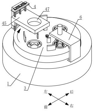
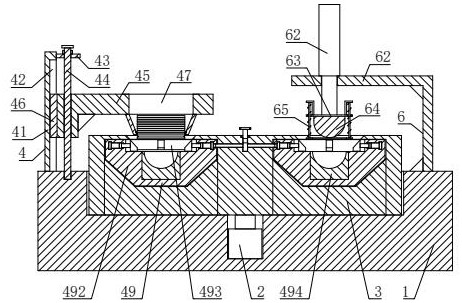
[0036] see figure 1 and figure 2 , a metal shell stamping and forming device for lighting lamps, including a workbench 1, an intermittent motor 2, a support base 3, a discharging part 4 and a stamping part 6, the upper end of the workbench 1 is provided with a circular chute, the circular chute An installation groove is opened at the bottom and at the center, the intermittent motor 2 is arranged in the installation groove, and a support seat 3 is rotated in the circular chute. Parts, the bottom of the support seat 3 is connected with the output shaft of the intermittent motor 2, and the upper end of the support seat 3 is evenly provided with a plurality of processing grooves along its circumferential direction, and the left and right sides of the upper...


PUM


Abstract

The invention relates to the technical field of lighting lamps, in particular to a lighting lamp metal shell punch forming device which comprises a workbench, an intermittent motor, a supporting base, a discharging part and a punching part. An existing stamping die has the following problems that an aluminum sheet cannot be guided and limited by the stamping die, so that the aluminum sheet cannot be accurately moved into a lower die, and the stamping effect on the aluminum sheet is easily affected; in the stamping process, the aluminum sheet cannot be limited, so that the aluminum sheet is prone to deviation, and the stamping precision of the aluminum sheet is affected. According to the metal plate punching device, a metal plate can be guided through the multiple guide blocks, so that the metal plate accurately falls to the position above the receding groove, and the punching effect on the metal plate is enhanced; in the stamping process of the metal plate, the metal plate can be pressed and fixed, so that the metal plate is prevented from deviating in the stamping process, and then the stamping precision can be improved.

Description

technical field [0001] The invention relates to the technical field of lighting lamps, in particular to a stamping and forming device for metal shells of lighting lamps. Background technique [0002] Lighting lamps can be divided into chandeliers, table lamps, wall lamps, floor lamps, etc. In order to improve the safety of lamps, people usually install lamp housings on lamps, which can also prevent ash from falling on the lamps, and lamp casings are generally divided into plastic casings and a metal shell, wherein the metal shell is made by stamping a metal plate. [0003] The existing stamping die has a complex structure, a single function, and the specification of the die is not easy to adjust, and the scope of application is small. Solutions that can solve the above problems are provided in the prior art. For example, the Chinese invention patent application with the application number of 202011274406.0 discloses a stamping die for producing LED lamp housings. Below the...

Claims


Application Information

Patent Timeline
IPC IPC(8): B21D22/08B21D43/00B21D43/02
CPCB21D22/08B21D43/003B21D43/02
Inventor 张平
Owner 江苏烨明光电有限公司
Why Eureka
Try Eureka