Paper pressing roller transmission device

A transmission device and paper pressing roller technology, which is used in transportation and packaging, thin material handling, object supply, etc., can solve the problems of inability to transport paper, high pressure, and different rotational speeds of the upper and lower paper pressing rollers. Ensure equipment stability and service life, simple control logic, and reduce paper scratches

Pending Publication Date: 2022-07-01
MASTERWORK GROUP CO LTD
View PDF0 Cites 0 Cited by
  • Summary
  • Abstract
  • Description
  • Claims
  • Application Information

AI Technical Summary

Problems solved by technology

In view of the common problems such as warping of paper to be die-cut at present, in order to ensure that the paper can pass through the platen roller smoothly, structures such as connecting rods or cams are usually used to enable the platen roller to move up and down vertically. However, in these structures, due to the upper The center distance between the platen roller and the lower platen roller changes in real time. The upper platen roller is usually in the form of no power, which will cause the paper that originally needs to rely on the joint action of the upper platen roller and the lower platen roller to appear. The pressure between the lower platen roller is too large, which eventually leads to surface collapse; or the pressure between the upper platen roller and the lower platen roller is too small, which eventually causes the paper to fail to be conveyed; and the speed difference between the upper platen roller and the lower platen roller causes the paper to slip , scratches, etc.
Even if a separate power source can be added to the upper platen roller, there will still be deviations due to the drive of different power sources, and there will still be corresponding problems caused by the different speeds of the upper platen roller and the lower platen roller

Method used


Image

  • Paper pressing roller transmission device
  • Paper pressing roller transmission device
  • Paper pressing roller transmission device

Examples


Embodiment Construction

[0037] Figure 1-4 and the following descriptions describe alternative embodiments of the invention to teach those skilled in the art how to implement and reproduce the invention. In order to teach the technical solutions of the present invention, some conventional aspects have been simplified or omitted. Those skilled in the art will appreciate that modifications or substitutions derived from these embodiments will fall within the scope of the present invention. Those skilled in the art will appreciate that the following features can be combined in various ways to form various variations of the invention. Thus, the present invention is not limited to the alternative embodiments described below, but only by the claims and their equivalents.

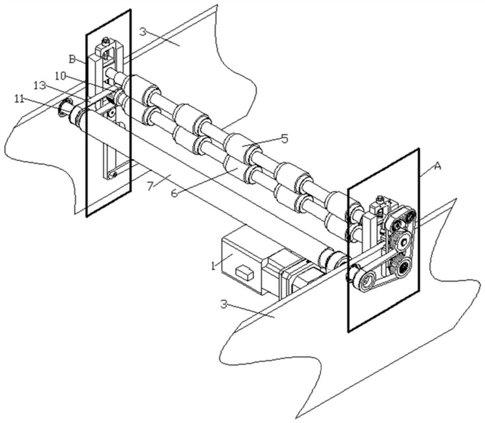
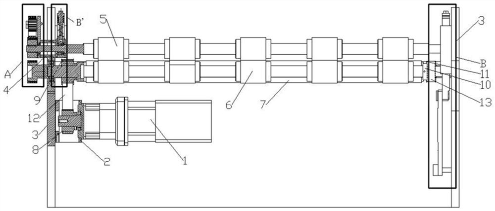
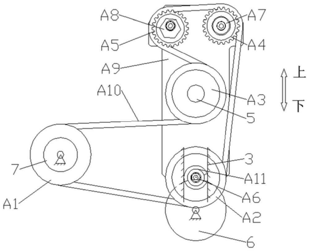
[0038] like figure 1 As shown, it is a schematic diagram of the structure of the paper platen roller transmission device of the present invention, figure 2 It is the front view of the paper pressing roller transmission device of the ...


PUM


Abstract

The invention provides a paper pressing roller transmission device. The paper pressing roller transmission device comprises a motor, a rack, an upper paper pressing roller, a lower paper pressing roller, a paper conveying table driving shaft and a guide block device. The upper paper pressing roller, the lower paper pressing roller and the paper conveying table driving shaft are arranged on the rack in parallel and can rotate relative to the rack, and the motor is arranged on the rack and used for providing power for rotation of the upper paper pressing roller, the lower paper pressing roller and the paper conveying table driving shaft; the guide block device is arranged on the machine frame, connected with the upper paper pressing roller and used for driving the upper paper pressing roller to vertically slide along the machine frame. According to the device, real-time constant-speed reverse rotation of the upper paper pressing roller and the lower paper pressing roller can be achieved, paper slipping is avoided, and paper scratching caused by paper slipping is reduced; the paper squeezing pressure of the upper paper pressing roller and the lower paper pressing roller is adjustable, and the problems that the paper is damaged due to overlarge pressure of the upper paper pressing roller and the lower paper pressing roller or the paper cannot be conveyed due to oversmall pressure are solved; the upper paper pressing roller, the lower paper pressing roller and the paper conveying table driving shaft share the same power source, and the motion law can be kept consistent.

Description

technical field [0001] The present invention relates to a paper conveying device, in particular, to a platen roller transmission device. Background technique [0002] In the existing paper pressing roller transmission devices installed in the die-cutting machine, the paper is pressed by the upper paper pressing roller and the lower paper pressing roller, and the paper is conveyed by the friction force between the paper pressing roller and the paper. In view of the common problems such as warping of the paper to be die-cut at present, in order to ensure that the paper can pass through the platen roller smoothly, structures such as connecting rods or cams are usually used, so that the platen roller can move vertically up and down. The center distance between the platen roller and the lower platen roller changes in real time. The upper platen roller is usually in the form of no power, which will cause the paper that needs to be transported by the joint action of the upper plate...

Claims


Application Information

Patent Timeline
Patent Type & Authority Applications(China)
IPC IPC(8): B65H5/06B65H26/00
CPCB65H5/062B65H5/068B65H26/00B65H2701/1924
Inventor 杨德志乔龙吕永娜
Owner MASTERWORK GROUP CO LTD
Why Eureka
Try Eureka