
Digital printing heat transfer printing machine

A heat transfer machine and digital printing technology, applied in printing machines, rotary printing machines, printing, etc., can solve the problems of no heat dissipation treatment, twisting and loosening of cloth rolls, affecting printing quality, etc., and achieve simple and reliable equipment structure , Improve work efficiency and facilitate maintenance

Pending Publication Date: 2022-07-01
厦门高准工贸有限公司
View PDF0 Cites 1 Cited by
  • Summary
  • Abstract
  • Description
  • Claims
  • Application Information

AI Technical Summary

Problems solved by technology

[0006] Aiming at the deficiencies of the prior art, the present invention provides a digital printing thermal transfer machine, which solves the problem of printing medium and large cloth rolls. Due to the simple structure design, the cloth rolls are prone to twisting and loosening during the printing process, and the thermal After the transfer is completed, since there is no heat dissipation treatment, it is easy to cause scratches on the printed pattern during the fabric winding process, which will affect the overall printing quality.

Method used

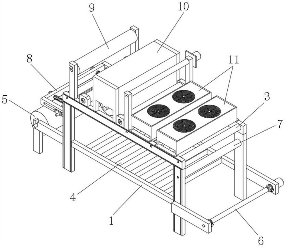
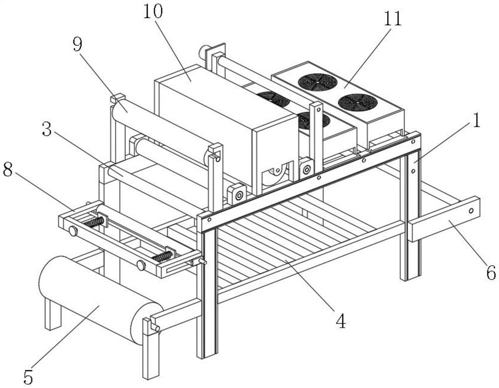
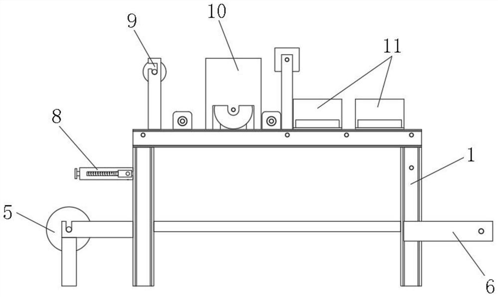

Image

  • Digital printing heat transfer printing machine
  • Digital printing heat transfer printing machine
  • Digital printing heat transfer printing machine

Examples


Embodiment Construction

[0043] The technical solutions in the embodiments of the present invention will be clearly and completely described below with reference to the accompanying drawings in the embodiments of the present invention. Obviously, the described embodiments are only a part of the embodiments of the present invention, but not all of the embodiments. Based on the embodiments of the present invention, all other embodiments obtained by those of ordinary skill in the art without creative efforts shall fall within the protection scope of the present invention.

[0044] In the description of the present invention, it should be noted that the terms "center", "upper", "lower", "left", "right", "vertical", "horizontal", "inner", "outer", etc. The indicated orientation or positional relationship is based on the orientation or positional relationship shown in the accompanying drawings, which is only for the convenience of describing the present invention and simplifying the description, rather than ...


PUM


Abstract

The invention provides a digital printing heat transfer printing machine, and relates to the technical field of heat transfer printing. The digital printing thermal transfer printing machine comprises a fixed rack, one side of the center of the top of the fixed rack is fixedly connected with a thermal printing supporting plate, the top of the center of the fixed rack is rotationally connected with a plurality of conveying roller shafts, and the bottom of one end of the fixed rack is fixedly connected with a cloth roll feeding mechanism; the bottom of the other end of the fixed rack is fixedly connected with a cloth roll receiving mechanism, the center of the end, close to the cloth roll feeding mechanism, of the fixed rack is fixedly connected with an elastic extension mechanism, and a transfer printing film feeding and rolling mechanism is arranged on one side of the top of the fixed rack. Through the simple design of the cloth roll feeding mechanism, the cloth roll receiving mechanism, the elastic extension mechanism, the transfer printing film feeding and rolling mechanism, the hot-pressing roll printing mechanism and the cooling mechanism, normal heat transfer printing machining work can be completed, meanwhile, rapid heat dissipation and cooling can be conducted on cloth rolls after hot printing is completed, and the cloth rolls are prevented from being scratched in the subsequent rolling process.

Description

technical field [0001] The invention relates to the technical field of thermal transfer printing, in particular to a digital printing thermal transfer printing machine. Background technique [0002] Thermal transfer machine is a general term for machines used in thermal transfer technology. Thermal transfer machines include flat heat transfer machines, high pressure heat transfer machines, shaking head heat transfer machines, roasting cup machines, roasting pan machines, roasting cap machines and other thermal transfer printing machines. The machine can print a wide range of heat transfer, including flat heat transfer, as well as surface heat transfer such as cups, plates, and hats. Therefore, heat transfer is also called sublimation. The process is to use heat transfer for any pictures such as portraits and landscapes. The printing ink is printed on ordinary paper or high-precision printing paper, and then heated to a certain temperature within a few minutes by the correspo...

Claims


Application Information

Patent Timeline
Patent Type & Authority Applications(China)
IPC IPC(8): B65H20/02B65H18/02B65H18/14B65H16/06B41F16/02B41F16/00B41F23/04
CPCB65H20/02B41F16/02B41F16/0026B41F16/0093B41F23/0476B65H18/02B65H18/14B65H18/028B65H16/06B65H2701/10
Inventor 陈缘霖陈伟煌
Owner 厦门高准工贸有限公司
Learn More