Gate-type working tank of high-speed steel strip continuous nickel plating unit

A working tank and high-speed steel technology, which is applied in plating tanks, electrolytic components, electrolytic processes, etc., can solve the problems of long time for adding nickel and changing width specifications, fast nickel consumption, and long maintenance time, so as to shorten maintenance time and improve The effect of increasing work efficiency and circulation volume

Pending Publication Date: 2022-07-01
江苏东方九天新能源材料有限公司
0 Cites 0 Cited by

AI-Extracted Technical Summary

Problems solved by technology

[0003] 1) It takes a long time to add nickel and change width specifications, which affects production efficiency
[0004] The lower part of the tank body 4 is equipped with sinking roller 5, and the upper part of the tank body is equipped with conductive roller 9 and other devices. Due to the fast production line speed and high output, nickel consumption in the anode titanium basket in the working tank is fast, and nickel needs to be added again after 5 days of production. Every time you add nickel blocks, you must stop the machine and remove the conductive roller and other equipment above the working tank, remove the anode bridge and the anode titanium basket screws, and then use the crane to lift out the anode titanium basket. After lifting out, first clean the anode titanium basket and clean the titanium basket. The outer anode bag, then add nickel block to each anode titanium basket, install the anode bag on the titanium basket after filling, and then hoist it to the working tank for installation, and then install the upper conductive roller, the whole unit has a total of 16 electroplating work There are four integral anode components in each tank body, and each anode component filled with nickel weighs more than 400 kilograms. Once nickel ...

Method used

As shown in Figures 5 and 6, the quick lock door mechanism 3 includes a door frame locator 3-1 and a compression connector 3-2, and the door frame locator 3-1 is connected to the groove body 4 On the front side plate, the compression connector 3-2 is tightly pressed on the door 1 through a plurality of transfer fixing plates, and the door frame positioning member 3-1 and the compression connector 3-2 are arranged in parallel, The transfer fixing plate includes at least two first transfer fixing plates 3-3 on the upper part and a second transfer fixing plate 3-5 at the bottom, and the first transfer fixing plate 3-3 and the second transfer fixing plate The connection fixing plates 3-5 are parallel and evenly distributed, and one end of the first transfer fixing plate 3-3 and the second transfer fixing plate 3-5 is hinged on the door frame positioning member 3-1 through a positioning pin, so The other ends of the first transfer fixing plate 3-3 and the second transfer fixing plate 3-5 are hinged on the compression connector 3-2 through positioning pins, and the sides of the second transfer fixing plate 3-5 are connected There are 3-4 handles. In the closed state, as shown in Figure 6, the door frame positioning part 3-1 and the compression connector 3-2 are dislocated and arranged in parallel, and the handle 3-4 drives all the transfer fixing plates through the compression connector 3-2 to move from the vertical The state changes to a horizontal state and is pressed on the door 1; when it is opened, the handle 3-4 drives all the transfer fixing plates to move in the reverse direction by pressing the connecting piece 3-2 to a vertical state away from the door, and at this time the pressing connection Part 3-2 is positioned at the outer side of door frame positioning part 3-1 and both are still kept parallel. The setting of the fast locking mechanism 3 makes the opening and closing operation of the door faster and more convenient. In addition, a first gasket 7 is provided on the inner side of the door 1, and the arrangement of the first gasket can ensure the sealing of the joint after the door is closed.
In addition, described mounting flange 12-3 adopts steel plate cutting to be square, and the cente...

Abstract

The invention discloses a gate-type working tank of a high-speed steel strip continuous nickel plating unit, the top of the working tank is provided with a conductive roller, the bottom of the working tank is provided with a sink roller, and the cavity of the working tank is internally provided with an anode bridge and an anode assembly; the front side face of a tank body of the working tank is of an opening structure, two doors are connected to the opening of the front side face of the tank body, the tank body is divided into a top square cavity and a bottom conical cavity, the sink roller is installed at the conical cavity, and a liquid outlet and an electroplating liquid inlet pipe assembly are arranged on the front side wall and the rear side wall of the conical cavity. A backflow groove is formed in the upper portion of the top square cavity and connected with an overflow opening, and the overflow opening is formed in the side back to the door. The device is ingenious in conception, nickel adding or replacing operation of the anode assemblies is achieved through the design of the doors on the side faces and the auxiliary trolley, the auxiliary trolley can support the four anode assemblies at a time, the time for replacing or maintaining the anode assemblies every time is greatly shortened, and the working efficiency is greatly improved.

Application Domain

Tanks

Technology Topic

Electrically conductiveEngineering +3

Image

  • Gate-type working tank of high-speed steel strip continuous nickel plating unit
  • Gate-type working tank of high-speed steel strip continuous nickel plating unit
  • Gate-type working tank of high-speed steel strip continuous nickel plating unit

Examples

  • Experimental program(1)

Example Embodiment

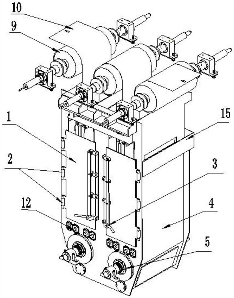
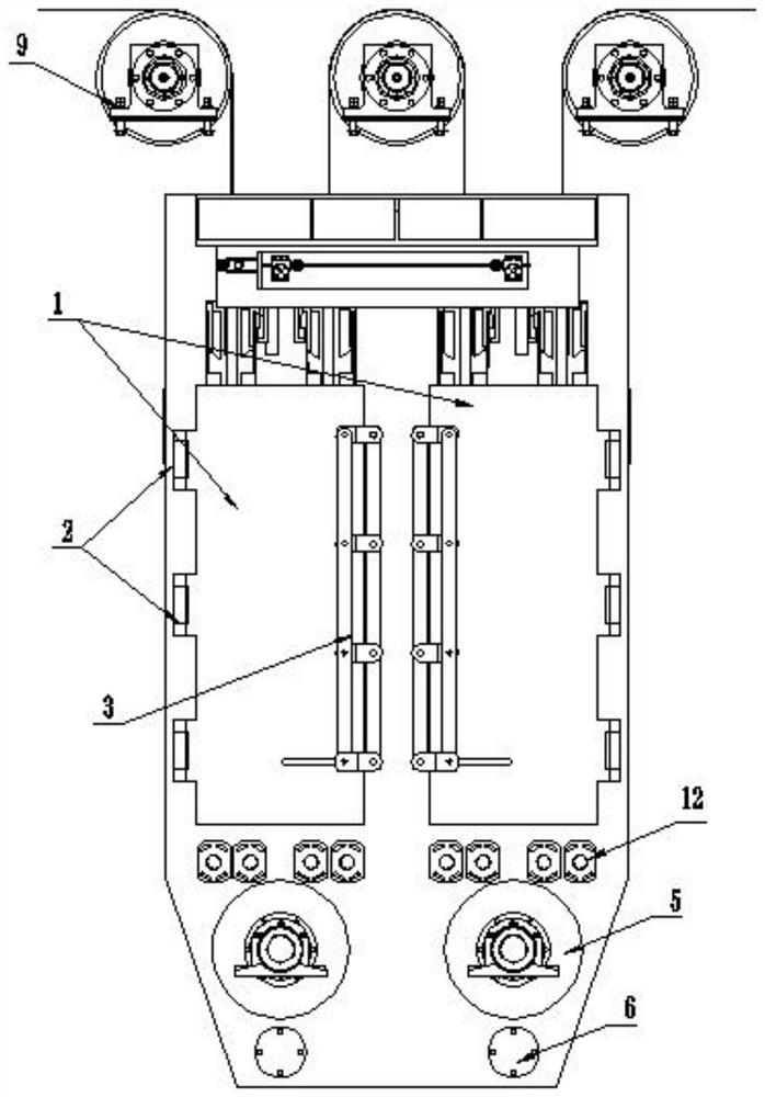
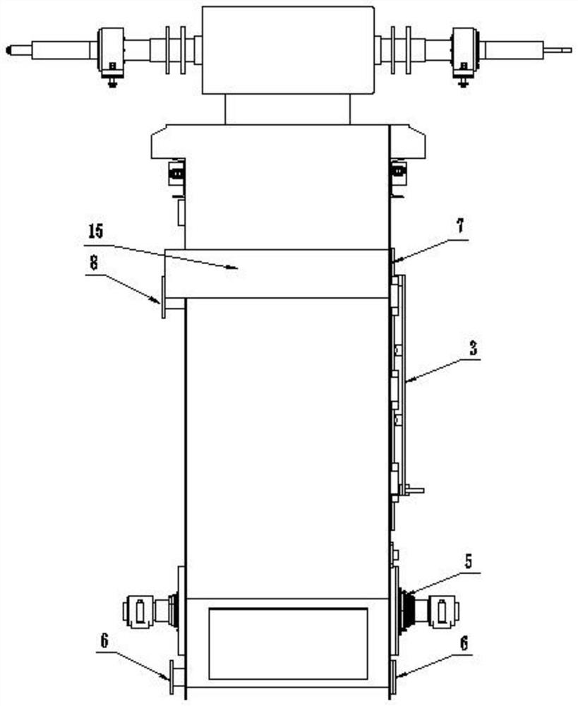
[0038] like Figure 1-4 As shown, a door-type working tank of a high-speed steel strip continuous nickel plating unit is installed with a conductive roller 9 at the top of the working tank, a sinking roller 5 is installed at the bottom, and an anode bridge 14 and an anode are installed inside the cavity of the working tank. Assembly 11, the steel strip 10 enters from one end and goes around the three conductive rollers 9 and the two submerged rollers 5 placed in dislocation in turn, and then extends from the other side, and the steel strip 10 from each set of symmetrically arranged anode bridges 14 and anode assemblies Pass through between 11; the front side of the tank body 4 of the working tank is set as an opening structure, and two doors 1 are connected to the opening of the front side of the tank body 4, and the tank body 4 is divided into a top square cavity and a bottom The conical cavity has two parts. The sinking roller 5 is installed at the conical cavity. The front and rear side walls of the conical cavity are provided with a liquid discharge port 6 and an electroplating liquid inlet pipe assembly 12. The top square cavity The upper part of the door is provided with a backflow groove 15 , the backflow groove 15 is connected with an overflow port 8 , and the overflow port 8 is arranged on the side facing away from the door 1 .
[0039] Specifically, the side of the connecting end of the door 1 is connected to the opening of the front side of the groove body 4 through the hinge 2 , and the side of the free end of the door 1 is provided with a quick locking mechanism 3 .
[0040] like Figure 5 , 6As shown, the quick lock door mechanism 3 includes a door frame positioning member 3-1 and a pressing connecting member 3-2, the door frame positioning member 3-1 is connected to the front side plate of the slot body 4, and the pressing The tight connector 3-2 is pressed on the door 1 by a plurality of transfer fixing plates, and the door frame positioning member 3-1 and the pressing connector 3-2 are arranged in parallel, and the transfer fixing plate includes an upper part. At least two first transfer fixing plates 3-3 and one second transfer fixing plate 3-5 at the bottom, the first transfer fixing plate 3-3 and the second transfer fixing plate 3-5 are parallel cloth, and one end of the first adapter fixing plate 3-3 and the second adapter fixing plate 3-5 is hinged on the door frame positioning member 3-1 through a positioning pin, and the first adapter fixing plate 3-5 -3 and the other end of the second transfer fixing plate 3-5 are hinged on the pressing connector 3-2 through a positioning pin, and a handle 3-4 is connected to the side of the second transfer fixing plate 3-5. closed, such as Image 6 As shown, the door frame positioning member 3-1 and the pressing connection member 3-2 are arranged in parallel in dislocation, and the handle 3-4 drives all the transfer fixing plates from the vertical state to the horizontal state through the pressing connection member 3-2 and presses the Tighten on the door 1; when opened, the handle 3-4 drives all the transfer fixing plates to move in the reverse direction to the vertical state away from the door through the pressing connector 3-2, and the pressing connector 3-2 is positioned at the door frame at this time. the outside of the piece 3-1 and the two remain parallel. The setting of the quick door locking mechanism 3 makes the operation of opening and closing the door more rapid and convenient. In addition, the inner surface of the door 1 is provided with a first sealing gasket 7, and the arrangement of the first sealing gasket can ensure the tightness of the joint after the door is closed.
[0041] The reflow tank 15 surrounds three sides of the tank body 4 , and the side of the tank body 4 on which the door 1 is installed does not have the reflow tank 15 to ensure smooth reflow of the electroplating solution.
[0042] like Figure 4 As shown in the figure, two liquid discharge ports 6 are provided on the inner side and are located below the sinking roller 5. The electroplating solution liquid inlet pipe assembly 12 is provided with eight groups and is located above the sinking roller 5. Each two groups It is a unit and arranged symmetrically.
[0043] like Figure 7 As shown, the electroplating liquid inlet pipe assembly 12 includes a liquid inlet pipe 12-1 and a nozzle 13, and a plurality of the nozzles 13 are evenly connected to the liquid inlet pipe 12-1, and the liquid inlet pipe 12- One end of 1 is located in the cavity of the working tank and is connected to the inner wall of the tank body 4 through the retaining ring 12-2. The other end of the liquid inlet pipe 12-1 penetrates the tank body 4 on the other side and is installed by the method The flange 12-3 is positioned, and the mounting flange 12-3 is connected to the outer side wall of the groove body 4 by fixing screws 12-4.
[0044] Specifically, a second sealing gasket 12-5 for sealing is provided between the mounting flange 12-3 and the outer side wall of the groove body 4. The design of the second sealing gasket 12-5 effectively ensures the The tightness of the connection of the liquid pipe 12-1 prevents the overflow of the electroplating solution at the connection. Specifically, the material of the liquid inlet pipe 12-1 and the nozzle 13 is high temperature resistant PP, and the material of the second gasket 12-5 is fluorine rubber.
[0045] In addition, the mounting flange 12-3 is cut into a square shape from a steel plate, the center of the mounting flange 12-3 is provided with a circular through hole for positioning the liquid inlet pipe 12-1. There are four arc-shaped via holes for fixing screws 12-4 around. The design of four arc-shaped via holes improves the convenience of connection and avoids the misalignment of the circle center when the round hole is matched with the round hole. At the same time, the design can facilitate the adjustment of the installation position of the liquid inlet pipe 12-1, thereby driving the nozzle 13 to rotate, adjusting the spraying direction of the electroplating solution, and better ensuring the nickel plating effect.
[0046] The electroplating liquid inlet pipe assembly 12 is set as a direct injection liquid inlet pipe, and the liquid inlet pipe 12-1 is installed above the submerged roller 5 to eliminate the occlusion of the submerged roller 5 for the plating solution circulation. The nozzle 13 installed on the liquid inlet pipe Aiming at the electroplating area of ​​the steel strip 10 greatly increases the circulation volume of the electroplating solution in the electroplating area, ensuring the content of nickel ions in the electroplating solution. Under the condition that the electroplating layer reaches 3um, the current density can continue to increase, so that the high-speed steel The speed of the belt continuous nickel plating unit has also been further increased.
[0047] The working process of the present invention is as follows:
[0048] First of all, when the production line is in normal production, the steel strip 10 runs in one direction in the working tank. At this time, the door 1 is closed, the conductive roller 9 is connected to the cathode power supply and transmitted to the steel strip 10, the anode bridge 14 is connected to the anode power supply, and the anode bridge is connected. The anode assembly 11 is composed of a titanium basket and an anode bag. The nickel block is contained in the titanium basket. At this time, the nickel block is connected to the anode power supply, and the electroplating solution is supplied by the pump and enters the working tank from the electroplating solution inlet pipe 12-1. , and is sprayed between the anode and the cathode by the nozzle 13. After the liquid level of the electroplating solution reaches a certain high level, it all flows into the reflux tank 15, and then overflows into the underground storage tank through the overflow port 8 through the reflux tank. cycle. After the steel strip connected with the cathode power supply enters the working tank, due to the action of the current and the electroplating solution, nickel ions are deposited on the cathode steel strip 10, and the steel strip 10 is plated with nickel.
[0049] When the working tank needs maintenance, just shut down the electroplating solution pump, turn off each power supply, open the four drain ports 6 on the side, and drain the electroplating solution into the underground storage tank. After the electroplating solution is finished, the door can be locked quickly The handle 3-4 of the mechanism 3 opens the door, and the internal parts of the working tank can be cleaned, washed and maintained, and the devices such as the conductive roller 9 need not be disassembled. Specifically, the underground storage tank is located in a tank body in the basement of the equipment, and the working tank is two separate parts. It is mainly used for the storage and circulation of the electroplating solution. After the normal shutdown, the electroplating solution in the working tank will be discharged into the underground. In the storage tank, the electroplating solution is also added to the underground storage tank before starting the machine. During normal startup, the electroplating solution is pumped from the underground storage tank to the electroplating solution inlet pipe assembly 12 and sprayed into the working tank through the nozzle. Liquid can be recycled.
[0050] like Figure 10 As shown in the figure, when it is necessary to replace the anode assembly 11 or add a nickel block, just remove the connecting screw on the transmission side of the anode bridge 14. Since the anode bridge is hung on the bracket of the tank body, it is only necessary to use the trolley support arm 18 to hold up the anode bridge 14. , and then slowly move out to the operating side. The auxiliary trolley 17 can be placed on one side of the tank body 4 and has the function of moving in six directions: up and down, left and right, and front and back. When the anode bridge 14 inside the tank body 4 and the anode assembly 11 connected below are removed, directly replace the new anode assembly prepared in advance, and then lift the anode bridge and the new anode assembly through the trolley support arm 18 and reload it into the Just specify the location. At present, the auxiliary trolley can hold four anode assemblies at a time, which greatly shortens the time for each anode assembly replacement or maintenance, so that the maintenance and replacement of anode assemblies or nickel addition time is only a quarter of the original time, which greatly improves the work efficiency.

PUM

no PUM

Description & Claims & Application Information

We can also present the details of the Description, Claims and Application information to help users get a comprehensive understanding of the technical details of the patent, such as background art, summary of invention, brief description of drawings, description of embodiments, and other original content. On the other hand, users can also determine the specific scope of protection of the technology through the list of claims; as well as understand the changes in the life cycle of the technology with the presentation of the patent timeline. Login to view more.

Similar technology patents

Novel power frequency inverter power supply in combined-type structure

PendingCN106877686Ashorten maintenance timeAvoid whole machine replacement
Owner:欧阳常青

Classification and recommendation of technical efficacy words

  • Improve work efficiency
  • Shorten maintenance time

Cooperation service platform facing different source data

InactiveCN101174957AImprove management level and qualityImprove work efficiency
Owner:NANJING UNIV OF FINANCE & ECONOMICS

Screw drilling tool, vertical drilling tool testing method and well inclination simulation testing equipment

InactiveCN111594144AReduced height requirementsImprove work efficiency
Owner:DEZHOU UNITED GASOLINEEUM MACHINERY

Method for intelligent automatic identification of transmission circuit parts

Owner:INFORMATION COMM COMPANY STATE GRID SHANDONG ELECTRIC POWER +2

Keyboard spill-proofing mechanism

ActiveUS7030330B2minimize manufacturing costimprove work efficiency
Owner:LITE ON SINGAPORE PTE LTD

Pipeline delivery pump

Owner:辽宁恒星泵业有限公司

Gas leakage detection method for engine cylinder

InactiveCN103542983Ashorten maintenance timeAvoid replacing normal components
Owner:UNITED AUTOMOTIVE ELECTRONICS SYST

Longitudinal tear detection device and method for conveying belt

Owner:河北省机电一体化中试基地有限公司
Why Eureka
Try Eureka