Stepless air volume adjusting device of reciprocating compressor

A gas volume adjustment and compressor technology, which is applied in the field of compressors, can solve problems such as inconvenient operation, and achieve the effect of convenient installation and rapid installation process

Pending Publication Date: 2022-07-01
TAIXING XINGHUA GAS VALVE CO LTD
View PDF5 Cites 0 Cited by
  • Summary
  • Abstract
  • Description
  • Claims
  • Application Information

AI Technical Summary

Problems solved by technology

[0004] Aiming at the deficiencies of the prior art, the present invention provides a stepless gas volume adjustment device for a reciprocating compressor, which has the advantages of more convenient disassembly and assembly, and solves the problem of inconvenient operation when regular disassembly and maintenance are required

Method used


Image

  • Stepless air volume adjusting device of reciprocating compressor
  • Stepless air volume adjusting device of reciprocating compressor
  • Stepless air volume adjusting device of reciprocating compressor

Examples


Embodiment 1

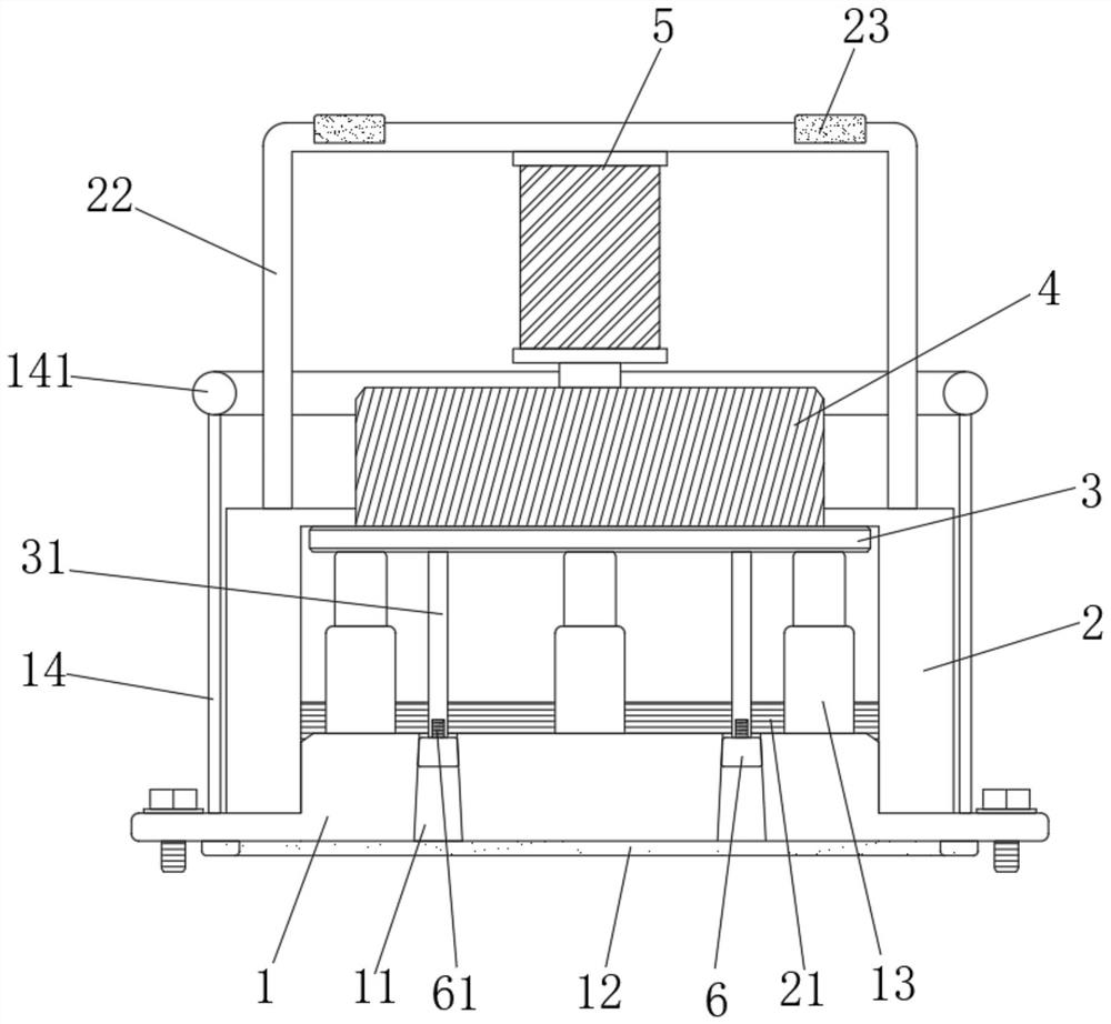
[0032] Example 1: see Figure 1-4 , the reciprocating compressor stepless air volume adjustment device of the present invention includes a valve seat 1, a connecting cylinder 2, a connecting plate 3, a hydraulic cylinder 5 and a piston 6, the surface of the valve seat 1 is provided with a plurality of air passages 11, the valve seat The surface of 1 is fixedly installed with a plurality of spring telescopic rods 13, the interior of the connecting cylinder 2 is opened as a cavity, the surface of the connecting cylinder 2 is engraved with a threaded road 21, the surface of the connecting cylinder 2 is fixedly connected with a fixing frame 22, and the connecting plate 3 The surface of the piston 6 is integrally formed with a connecting block 4, the surface of the connecting plate 3 is fixedly connected with a protruding rod 31, the hydraulic cylinder 5 is fixedly installed on the surface of the fixing frame 22, the surface of the piston 6 is provided with a threaded rod 61, and th...

Embodiment 2

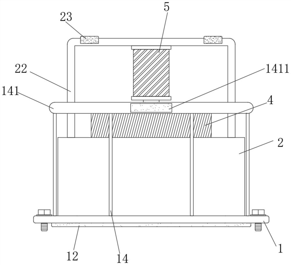
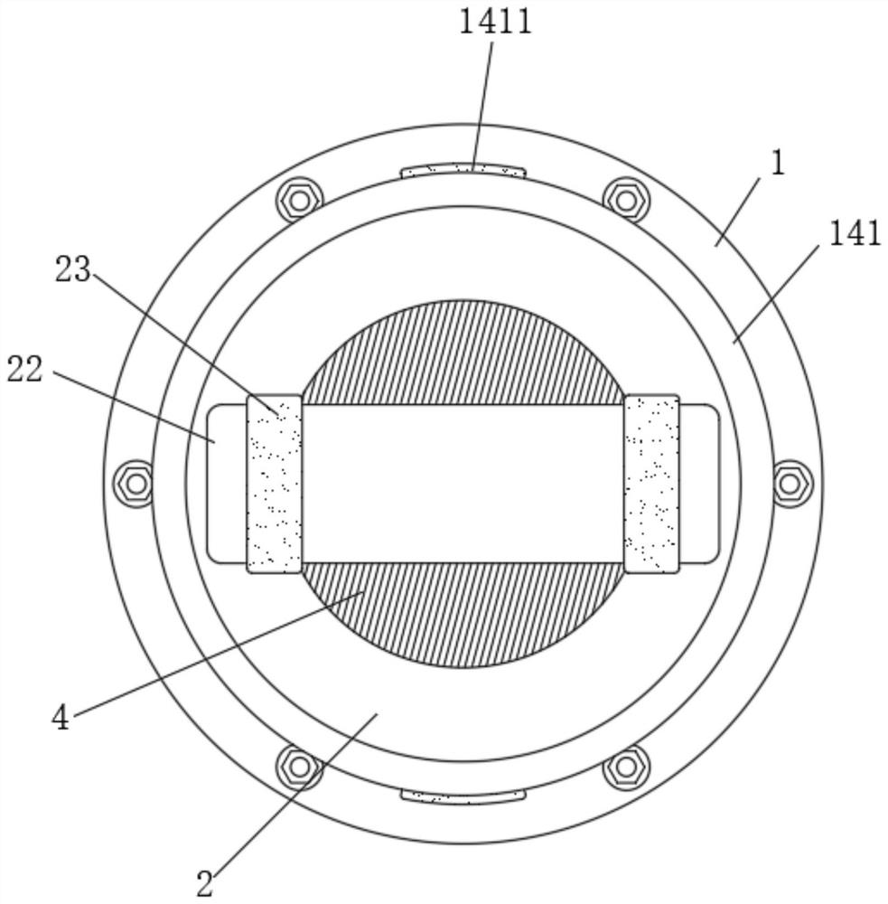
[0033] Example 2: Unlike Example 1, see Figure 1-4, the valve seat 1 protrudes into the interior of the connecting cylinder 2, the valve seat 1 and the connecting cylinder 2 are threadedly connected, the surface of the valve seat 1 is fixedly connected with a plurality of connecting rods 14 in the vertical direction, and the plurality of connecting rods 14 are connected along the annular The first grab bar 141 is fixedly connected, and the surface of the first grab bar 141 is engraved with anti-skid lines. The first grab rod 141 can be grasped to apply pressure, and the first grab rod 141 and the connecting rod 14 can be used to drive the valve seat 1 to rotate inside the connecting cylinder 2, so that the connection between the valve seat 1 and the connecting cylinder 2 is more secure. That's it.

Embodiment 3

[0034] Example 3: Unlike Example 1 or 2, see Figure 1-4 , the bottom surface of the valve seat 1 is fixedly connected with the rubber ring 12 along the ring, the two sides of the top surface of the fixing frame 22 are fixedly connected with the second rubber pads 23, and the front and back positions of the surface of the first grab bar 141 are fixedly connected with a second rubber pad 23. A rubber pad 1411, the front and back of the second rubber pad 23 protrude to the front and back positions of the fixing frame 22 respectively. During use, the installation between the valve seat 1 and the corresponding equipment is used to make the rubber ring 12 The valve seat 1 and the corresponding equipment are more stable under pressure and have a partial resilience. At the same time, during the inversion operation, the first rubber pad 1411 or the second rubber pad 23 can be effectively used to realize the device. The isolation effect from the corresponding support point prevents acc...


PUM


Abstract

The invention relates to the technical field of compressors, and particularly discloses a reciprocating compressor stepless air flow adjusting device which comprises a valve seat, a connecting cylinder, a connecting plate, a hydraulic cylinder and a piston, a plurality of ventilation channels are formed in the surface of the valve seat in a penetrating mode, a plurality of spring telescopic rods are fixedly installed on the surface of the valve seat, and a cavity is formed in the connecting cylinder; a threaded path is carved in the surface of the connecting cylinder, a fixing frame is fixedly connected to the surface of the connecting cylinder, a connecting block is integrally formed on the surface of the connecting plate, a protruding rod is fixedly connected to the surface of the connecting plate, and the hydraulic cylinder is fixedly installed on the surface of the fixing frame. Through the structural design of the position relation and the connection relation of the valve seat, the connecting cylinder, the connecting plate and the connecting block, a worker can disassemble and assemble the stepless air flow adjusting device and the valve seat more conveniently; therefore, a worker can maintain or overhaul all parts in the valve seat or the stepless air flow adjusting device more conveniently.

Description

technical field [0001] The invention relates to the technical field of compressors, in particular to a stepless air volume regulating device for a reciprocating compressor. Background technique [0002] The reciprocating compressor is a positive displacement compressor. It is a compressor that sequentially sucks and discharges the gas of a certain solvent into a closed space to increase the static pressure. During operation, the piston performs periodic reciprocating motion in the cylinder, and the space between the piston and the cylinder The space expands and shrinks periodically. When the space expands, the gas in the cylinder expands, the pressure decreases, and the gas is sucked in. When the space shrinks, the gas is compressed, the pressure rises, and a certain amount of gas is discharged. [0003] In order to keep the gas volume of the reciprocating compressor within a certain range during operation, it is necessary to use the stepless gas volume adjustment device of ...

Claims


Application Information

Patent Timeline
Patent Type & Authority Applications(China)
IPC IPC(8): F04B39/10F04B39/08F04B39/14F16K51/00
CPCF04B39/1013F04B39/08F04B39/14F16K51/00
Inventor 徐鹏徐兴华
Owner TAIXING XINGHUA GAS VALVE CO LTD
Why Eureka
Try Eureka