

Charging connector assembling equipment
A technology for charging connectors and assembly equipment, which is applied in the field of automation, can solve the problems of not being suitable for factory production needs, slow assembly speed, poor consistency, etc., and achieve the effect of easy insertion into the shrapnel fixing parts, fast speed, and stable combination
- Summary
- Abstract
- Description
- Claims
- Application Information
AI Technical Summary
Problems solved by technology
Method used
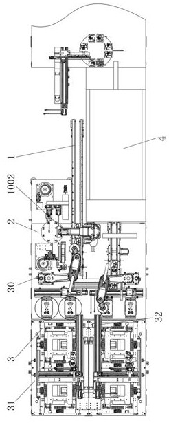
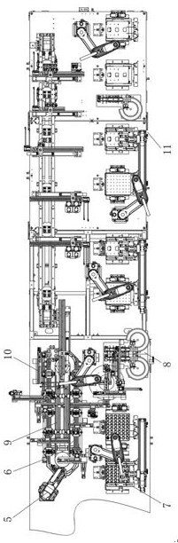
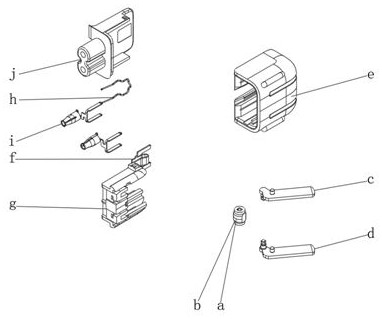
Image

Examples
Embodiment Construction
[0065] In order to make the purposes, technical solutions and advantages of the embodiments of the present invention clearer, the following will be described clearly and completely in combination with the technical solutions in the embodiments of the present invention. Obviously, the described embodiments are part of the embodiments of the present invention, and Not all examples.
[0066] In the description of the present invention, it should be understood that the terms "center", "horizontal", "portrait", "front", "rear", "left", "right", "top", "bottom", " The orientation or positional relationship indicated by vertical, horizontal, top, bottom, inner, outer, etc. is based on the orientation or positional relationship shown in the drawings, and is only for the convenience of describing the present invention and The description is simplified rather than indicating or implying that the device or element referred to must have a particular orientation, be constructed and operate...
PUM
 Abstract
Description
Claims
Application Information