Device for installing R pin

A technology for installing clips and rotating arms, which is applied in the direction of manufacturing tools and hand-held tools, etc., and can solve problems such as complicated procedures, power-off operations, and potential safety hazards

Active Publication Date: 2022-07-05
合肥矩特智能装备有限公司
View PDF7 Cites 0 Cited by
  • Summary
  • Abstract
  • Description
  • Claims
  • Application Information

AI Technical Summary

Problems solved by technology

This kind of close-range manual operation is not only complicated in process, but also requires power-off operation or wearing insulating clothing due to the existence of high-voltage current, which makes the whole operation a great safety hazard.

Method used


Image

  • Device for installing R pin
  • Device for installing R pin

Examples


Embodiment 1

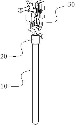
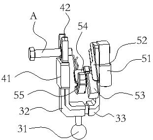
[0031] like Figure 1-2 A device for installing the R pin is shown, which is characterized in that it includes a clamping part for clamping the bolt A to be pressed and a distance adjusting part that can move close to and away from the clamping part; A rotatable rotating arm 52 is arranged on the part, the length direction of the rotating arm 52 extends radially along the bolt A to be pressed, and the rotation axis of the rotating arm 52 and the axis of the bolt A to be pressed are coaxial with each other; The straight stroke end of the rotating arm 52 performs a reciprocating linear motion in the longitudinal direction, a collet 54 is arranged on the straight stroke end, and the clamping mouth of the collet 54 constitutes a clamping end for clamping the tail end of the R pin; Positioning slot for the current position of the R pin.

[0032] A U-shaped mounting clip 30 is also included, and the U-shaped mounting clip 30 is composed of two working arms, namely a fixed arm 32 an...


PUM


Abstract

The invention belongs to the technical field of remote installation, and particularly discloses a device for installing an R pin. Comprising a clamping part used for clamping a to-be-pressed bolt and a distance adjusting part capable of moving close to or away from the clamping part. A rotatable rotating arm is arranged on the distance adjusting part, the length direction of the rotating arm extends in the radial direction of the to-be-pressed bolt, and the rotating axis of the rotating arm and the axis of the to-be-pressed bolt are coaxial with each other; a straight stroke end capable of doing reciprocating linear motion in the length direction of the rotating arm is arranged on the rotating arm, a clamping head is arranged at the straight stroke end, and a clamping opening of the clamping head forms a clamping end used for clamping the tail end of the R pin; a positioning groove used for orienting the current position of the R pin is formed in the clamping end. The device not only can replace manual short-distance installation of the R pin, but also is simple in structure and easy to use.

Description

technical field [0001] The invention belongs to the technical field of remote installation, in particular to a device for installing an R pin. Background technique [0002] At present, a large number of connecting bolts are provided on the transmission line, and the ends of the connecting bolts are provided with mounting holes in order to prevent the nuts from falling off, and R pins are installed in the mounting holes. Due to the snap connection between the R pin and the mounting hole, the R pin may be damaged and fall off as the usage time becomes longer. Generally, for this situation, manual close-range operation is required to re-install the damaged or fallen R-pin. This close-range manual operation is not only complicated, but also requires a power-off operation or wearing insulating clothing due to the existence of high-voltage current, which makes the entire operation a great safety hazard. Therefore, it needs to be solved urgently. SUMMARY OF THE INVENTION [00...

Claims


Application Information

Patent Timeline
Patent Type & Authority Applications(China)
IPC IPC(8): B25B27/08
CPCB25B27/08
Inventor 林帆徐秀华曹燕
Owner 合肥矩特智能装备有限公司
Why Eureka
Try Eureka