
Host positioning and mounting method based on block construction

A technology of positioning and installation, main engine, applied in the direction of ships, etc., can solve the problems affecting the smooth completion of engineering nodes, the difficulty of shafting load adjustment, affecting the installation efficiency of the main engine, etc., to achieve high industrial utilization value, shorten project construction time, and reduce site The effect of construction risk

Active Publication Date: 2022-07-05
JIANGNAN SHIPYARD GRP CO LTD
View PDF7 Cites 1 Cited by
  • Summary
  • Abstract
  • Description
  • Claims
  • Application Information

AI Technical Summary

Problems solved by technology

This method has obvious defects: since the main reduction gear device is elastically installed, that is, a vibration isolator is installed between the main reduction gear device and the base, and the vibration isolator needs to be pre-compressed, and the factors affecting the compression amount include the vibration isolator. Physical properties, temperature, time under pressure, weight under pressure, etc. Therefore, the position of the main reduction gear device may change greatly before and after the installation of the main engine, which will lead to the forced adjustment of the position of the main engine and shafting related equipment, resulting in The problem of the large number of active points in the shafting system and the difficulty in adjusting the shafting load will affect the installation efficiency of the main engine and the smooth completion of the project nodes

Method used


Image

  • Host positioning and mounting method based on block construction
  • Host positioning and mounting method based on block construction

Examples


Embodiment Construction

[0040] The embodiments of the present invention are described below through specific specific examples, and those skilled in the art can easily understand other advantages and effects of the present invention from the contents disclosed in this specification. The present invention can also be implemented or applied through other different specific embodiments, and various details in this specification can also be modified or changed based on different viewpoints and applications without departing from the spirit of the present invention.

[0041] When describing the embodiments of the present invention in detail, for the convenience of explanation, the cross-sectional views showing the device structure will not be partially enlarged according to the general scale, and the schematic diagrams are only examples, which should not limit the protection scope of the present invention. In addition, the three-dimensional spatial dimensions of length, width and depth should be included i...


PUM


Abstract

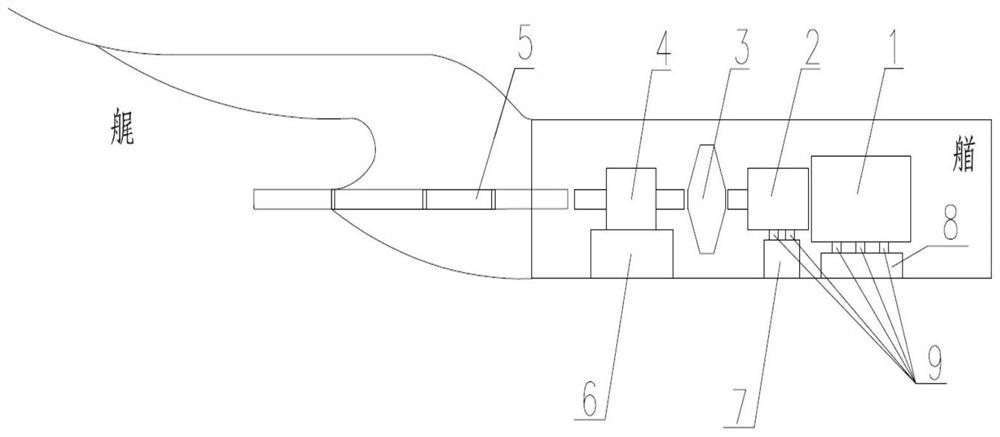
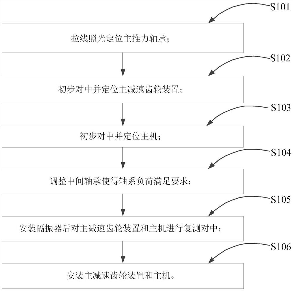
The invention provides a main engine positioning and mounting method based on block construction, which comprises the following steps of: firstly, determining the mounting position of a main thrust bearing by adopting a shafting stay wire irradiation method, then preliminarily determining the position of a main speed reduction gear device, preliminarily determining the mounting position of a main engine, and adjusting the shafting load, so as to finish the positioning and mounting of the main engine. And retesting and centering the main reduction gear device and the host, finally determining the mounting positions of the main reduction gear device and the host, and further finishing the mounting of the host. And meanwhile, the vibration isolator is pre-pressed for a period of time and then is adjusted and installed, so that system deviation caused by deformation generated by direct installation is avoided. According to the method, the problems that the number of shafting centering active points is large and the shafting load adjustment difficulty is large when a main engine is installed are solved, the engineering construction time is shortened, the ship construction efficiency is improved, meanwhile, the method is safe and efficient through field use feedback, the field construction risk is effectively reduced, and guarantee is provided for smooth completion of engineering nodes.

Description

technical field [0001] The invention relates to the technical field of ship construction, in particular to a main engine positioning and installation method based on total section construction. Background technique [0002] The general section construction method is currently a relatively advanced ship construction technology in the world, especially suitable for the construction of large civil ships. The general section construction of the hull usually divides the hull into multiple giant sections and builds them on different slipways at the same time. In the final stage of construction, the giant sections of the hull will be docked and assembled by gantry cranes in the large dock. The section docking is usually based on the midship or the general section adjacent to the midship, and is installed in sequence in the direction of the bow and stern. The advantage is the assembly and welding workload on the slipway. Less welding deformation is easy to control, which is conduciv...

Claims


Application Information

Patent Timeline
Patent Type & Authority Applications(China)
IPC IPC(8): B63B73/20B63B73/60
CPCB63B73/20B63B73/60
Inventor 张政刘邦宇赵梓安
Owner JIANGNAN SHIPYARD GRP CO LTD
Learn More