
Guide rail structure and chip testing machine

A technology of guide rail and driving mechanism, which is applied in the field of mobile guide rail and can solve problems such as displacement and deflection

Active Publication Date: 2022-07-05
HEBEI KTHAHCO TECH CO LTD
View PDF8 Cites 0 Cited by
  • Summary
  • Abstract
  • Description
  • Claims
  • Application Information

AI Technical Summary

Problems solved by technology

For the chip size manufactured by the manufacturer, the most common size is a rectangle. After the existing chip is processed, it needs to be tested by a testing agency to ensure the quality and performance of the chip. The existing testing method is usually to use a suction nozzle to place the chip on the carrier. For testing on the chip stage, at present, the visual positioning of the camera is mostly used, and the chip is grasped by the suction nozzle to offset in the XY direction, and the chip is placed on the test bench. However, when the chip is placed on the test bench, a certain displacement and The deflection of the angle, so the existing technology provides a kind of alignment member, through the movement of the alignment member to adjust the position and angle of the chip, and the alignment member needs to be driven in three directions when moving

Method used


Image

  • Guide rail structure and chip testing machine
  • Guide rail structure and chip testing machine
  • Guide rail structure and chip testing machine

Examples


Embodiment 1

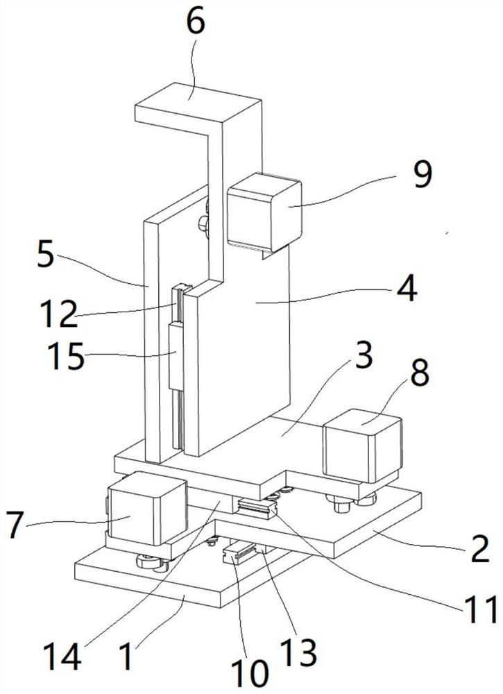
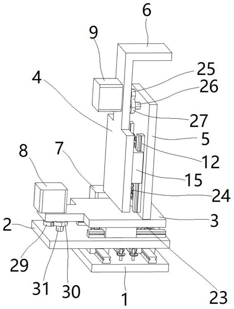
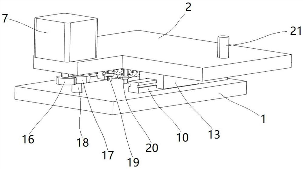
[0048] This embodiment provides a specific implementation of the guide rail structure, such as figure 1 and figure 2 As shown, it includes a mounting platform 1, a first substrate 2, a second substrate 3 and a third substrate 4. The first substrate 2 is slidably mounted on the mounting platform 1, the second substrate 3 is slidably mounted on the first substrate 2, and the third substrate 3 is slidably mounted on the first substrate 2. The base plate 4 is slidably mounted on the second base plate 3 , and a mounting portion 6 suitable for installing the positioning member protrudes from the third base plate 4 , and the sliding direction of the first base plate 2 , the sliding direction of the second base plate 3 and the third The sliding directions of the substrates 4 are perpendicular to each other. The first base plate 2 is provided with a first drive mechanism, and the drive end of the first drive mechanism is connected to the mounting platform 1; the second base plate 3 i...

Embodiment 2

[0065] This embodiment provides a specific implementation of a chip testing machine, including the guide rail structure in Example 1, the guide rail structure is installed on the testing machine, and an alignment member is installed on the mounting portion 6 on the guide rail structure, so that the The positioner adjusts the position and angle of the chips on the slide table.


PUM


Abstract

The invention provides a guide rail structure and a chip testing machine, and belongs to the technical field of mobile guide rails. A first substrate; a second substrate; the sliding direction of the first substrate, the sliding direction of the second substrate and the sliding direction of the third substrate are perpendicular to each other; a first driving mechanism; a second driving mechanism; and a third driving mechanism. According to the guide rail structure provided by the invention, the mounting part extends out of the third base plate, and under the driving of the first driving mechanism, the second driving mechanism and the third driving mechanism, the three base plates slide in a reciprocating manner to realize the front-back, left-right and up-down movement of the mounting part so as to drive the alignment piece to move front-back, left-right and up-down movement; and the position of the chip is corrected in the moving process of the alignment piece, so that the alignment piece can be conveniently subjected to displacement adjustment in three directions, and the position and the angle of the chip can be adjusted.

Description

technical field [0001] The invention relates to the technical field of moving guide rails, in particular to a guide rail structure and a chip testing machine. Background technique [0002] Integrated Circuit (IC), also known as microchip, chip or chip, is a way of miniaturizing circuits (including semiconductor devices, but also passive components, etc.), and is often fabricated on the surface of semiconductor wafers. [0003] With the development of the semiconductor industry, the thickness of integrated circuit chips is getting thinner and thinner, and the processing and detection accuracy of the chips are getting higher and higher. The most common size of the chip manufactured by the manufacturer is a rectangle. The existing chip needs to be tested by a testing agency after processing to ensure the quality and performance of the chip are qualified. The existing testing method usually uses a suction nozzle to place the chip on the carrier. For inspection on the film table...

Claims


Application Information

Patent Timeline
Patent Type & Authority Applications(China)
IPC IPC(8): B65G35/00B66F7/00
CPCB65G35/00B66F7/00
Inventor 孙国杰吕苏羲张焕德孙家琛
Owner HEBEI KTHAHCO TECH CO LTD
Learn More