
Treatment device for producing volatile organic pollutants

A volatile organic and pollutant treatment technology, applied in the direction of combustion types, lighting and heating equipment, incinerators, etc., can solve the problems of poor heat storage efficiency of ceramic regenerators, insufficient combustion of harmful gases, and increased external force, etc. Energy consumption, enhancement of combustion sufficiency, effect of complete combustion

Pending Publication Date: 2022-07-05
深圳市世邦环境科技有限公司
View PDF0 Cites 0 Cited by
  • Summary
  • Abstract
  • Description
  • Claims
  • Application Information

AI Technical Summary

Problems solved by technology

[0004] like Figure 14 As shown, in the working process of the existing RTO regenerative combustion furnace, the flow direction of organic matter is a, which enters the furnace body from bottom to top, discharges from top to bottom, and burns at port b: 1. The process of discharging harmful gases after combustion The heat storage efficiency of the ceramic regenerator is poor; 2. After the harmful gas is burned, the temperature of the carbon dioxide and water vapor produced by it is relatively high, and there is no external force. Down, the discharge direction is upward, and in order to make it contact with the ceramic regenerator, measures such as fans must be installed to change the discharge direction, and increasing the external force will increase energy consumption; 3. The fire source enters the combustion chamber through port b , the flames are concentrated in bundles. When burning, some harmful gases burn in direct contact with the flame, and some harmful gases burn in indirect contact with the flame, resulting in insufficient combustion of the harmful gas. In addition, the temperature of each part of the fire source deviates, which is even more Causes incomplete combustion of harmful gases

Method used


Image

  • Treatment device for producing volatile organic pollutants
  • Treatment device for producing volatile organic pollutants
  • Treatment device for producing volatile organic pollutants

Examples


Embodiment Construction

[0063]In order to further illustrate the technical means and effects adopted by the present invention to achieve the predetermined purpose of the invention, the specific embodiments, structures, features and effects of the present invention are described in detail below in conjunction with the accompanying drawings and preferred embodiments.

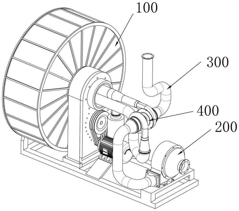
[0064] The existing RTO regenerative combustion furnace is mainly composed of a furnace body, a ceramic regenerative body and a combustion system, and is a harmful gas treatment equipment.

[0065] like Figure 14 As shown, the interior of the furnace body is composed of three ceramic medium regenerators and a common combustion chamber, from right to left are the first, second and third regenerators.

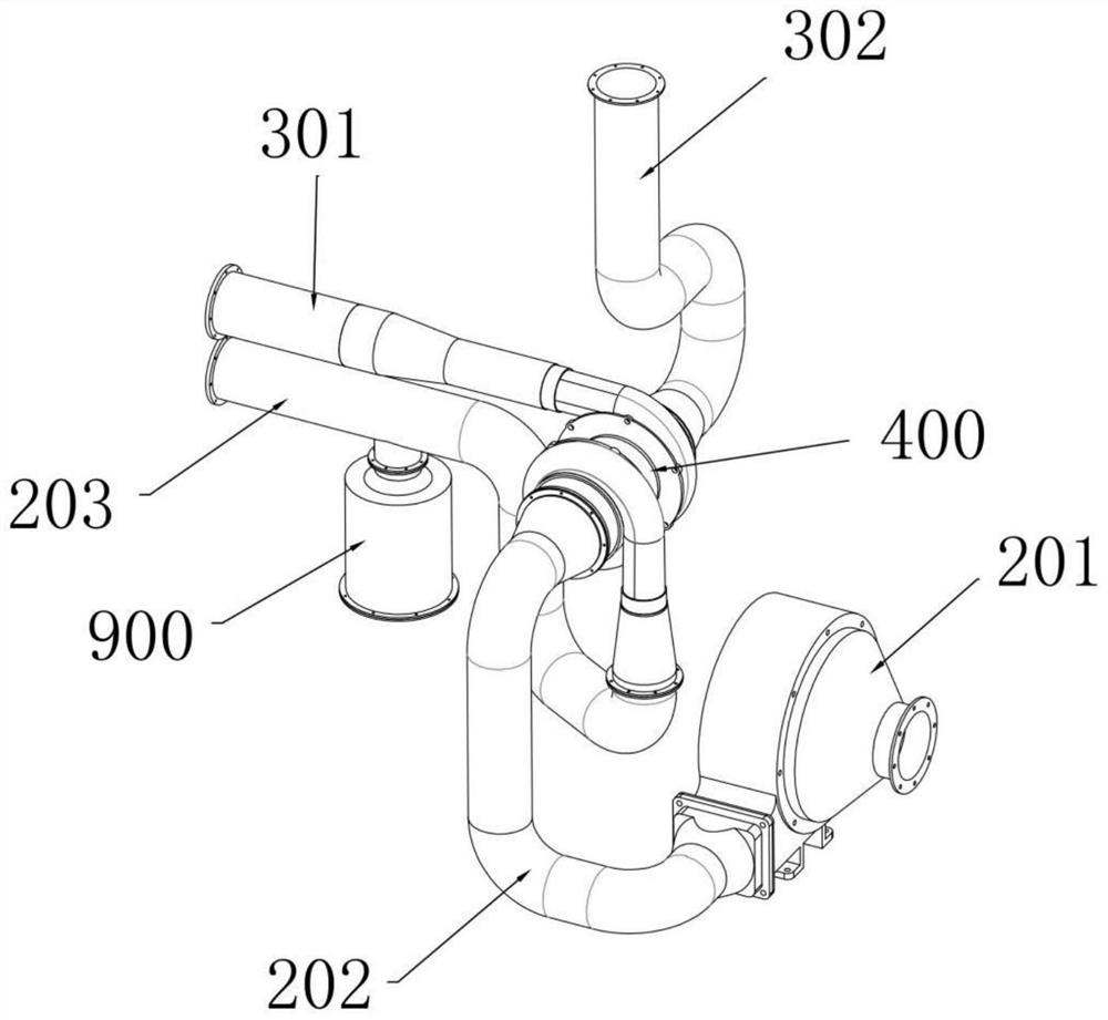
[0066] When working, the combustion chamber and the three regenerators work cyclically and in coordination. In the first stage: the harmful gas is sent to the regenerative chamber 1 through the induced draft fan. The heat is released, and ...


PUM


Abstract

The invention relates to a treatment device for producing volatile organic pollutants, belongs to the field of volatile organic compound treatment, and solves the problems that in the working process of an existing RTO heat storage type combustion furnace, the heat storage efficiency of a ceramic heat storage body is poor, the emission direction of carbon dioxide and water vapor is changed by increasing external force, and energy consumption is increased. The problem of insufficient combustion is solved; according to the scheme, the device comprises a frame body, the frame body is provided with a combustion system, an air inlet mechanism and a discharging mechanism, the air inlet mechanism is used for feeding volatile organic pollutants into the combustion system for combustion, the feeding direction of the air inlet mechanism is from bottom to top, the discharging mechanism is used for pulling substances generated by combustion to be discharged outwards, and the discharging direction of the discharging mechanism is from bottom to top; a combustion mechanism is arranged in the furnace body, a pipeline net set is arranged between the upper end and the lower end of the combustion mechanism, the combustion mechanism comprises a fire source unit and two heat storage units, and the two heat storage units are located on the upper side and the lower side of the fire source unit respectively.

Description

technical field [0001] The invention relates to the field of volatile organic pollutant treatment, in particular to the production of a volatile organic pollutant treatment device. Background technique [0002] Volatile organic pollutants are freely discharged into the air without treatment, which will pollute the environment and cause serious harm to human health. The treatment methods generally include direct combustion, biological filtration, and adsorption. [0003] Among them, the direct combustion method is to burn pollutants at high temperature to generate CO2 and H2O, and the RTO regenerative combustion furnace is used for combustion. [0004] like Figure 14 As shown, in the working process of the existing RTO regenerative combustion furnace, the flow direction of organic matter is a, which enters the furnace body from bottom to top, is discharged from top to bottom, and burns at port b: 1. The process of discharging harmful gas after burning 2. After the harmful g...

Claims


Application Information

Patent Timeline
IPC IPC(8): F23G7/06F23G5/44F23G5/46
CPCF23G7/066F23G5/44F23G5/46
Inventor 谢璀
Owner 深圳市世邦环境科技有限公司
Features
  • Generate Ideas
  • Intellectual Property
  • Life Sciences
  • Materials
  • Tech Scout
  • Unparalleled Data Quality
  • Higher Quality Content
  • 60% Fewer Hallucinations
Learn More