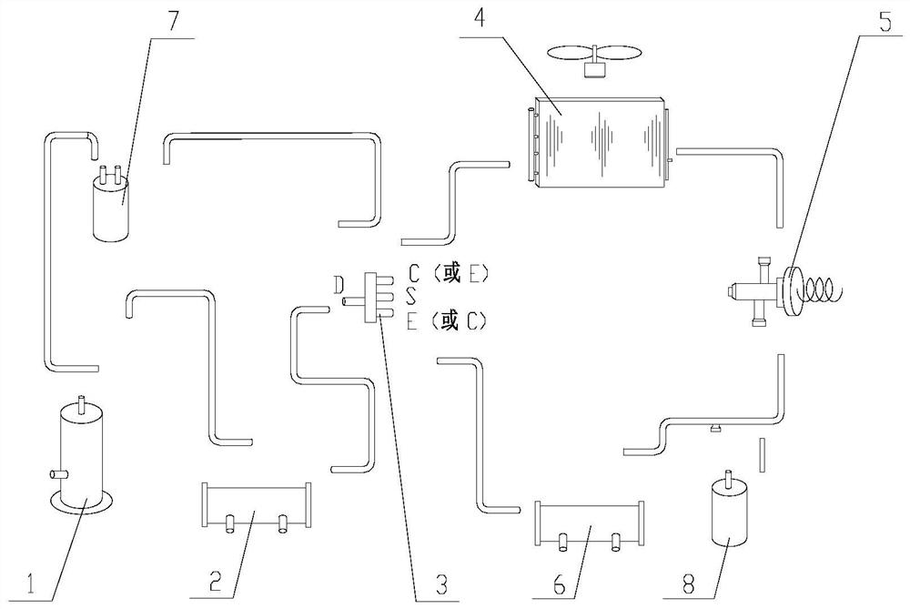
Triple heat supply pump unit with expansion liquid storage device
A technology of a liquid storage device and a pump unit, which is applied in the direction of compressors with reversible circulation, household heating, heating systems, etc. The effect of improving functional diversity and improving reliability
- Summary
- Abstract
- Description
- Claims
- Application Information
AI Technical Summary
Problems solved by technology
Method used
Image
Examples
Embodiment 1
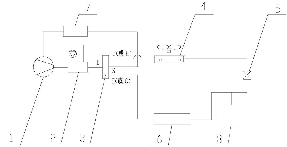
[0024] see figure 2, in the specific implementation process, it should be noted that when the system operates the refrigeration function, the gaseous refrigerant is discharged through the exhaust pipe of the compressor 1, and flows through the heat recovery device 2, and then enters from the D connection of the four-way reversing valve 3. The four-way reversing valve, and then flows into the air source heat exchanger 4 through the C interface of the four-way reversing valve (it should be noted that the C interface and the E interface of the four-way reversing valve 3 can be used interchangeably according to the designer's habits) After the refrigerant flows out of the air source heat exchanger, it is throttled through the first throttling member 5 and then enters the use-side heat exchanger 6. The liquid refrigerant absorbs the heat of the user's use-end in the use-side heat exchanger and then becomes gaseous refrigeration. The gaseous refrigerant enters the four-way reversin...
Embodiment 2
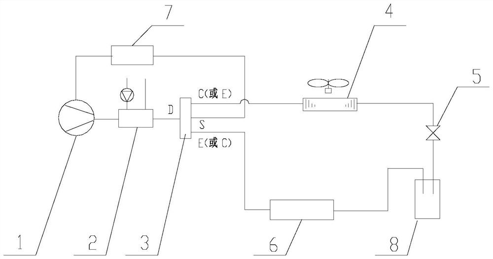
[0030] see image 3 , the accumulator with expansion liquid storage function is a double-pipe type liquid accumulator with expansion liquid storage function, and the double pipe type liquid accumulator with expansion liquid storage function ( Figure 7 ) On the basis of the single-pipe type liquid accumulator with expansion liquid storage function, the pipe b 8-5 is added, and the two refrigerant pipes are respectively connected with the throttling part interface and the use-side heat exchanger interface image 3 , the other connection methods are the same as those described in claim 1, and the working mode is basically the same as that of the first embodiment, the difference is that when the unit operates the refrigeration function or the refrigeration and hot water function, the first throttling member 5 comes out after throttling. The refrigerant enters the accumulator 8 from one of the refrigerant pipes, and then the refrigerant comes out from the other pipe of the accumul...
Embodiment 3
[0033] See Figure 4 , on the basis of Embodiment 1, a set of throttle components ( Figure 8 ) instead of the first throttling member 5, the working mode is basically the same as that of the first embodiment, and the different parts in the working mode are specifically, when the unit operates the refrigeration function or the refrigeration and hot water function, the air source heat exchanger 4 comes out. The refrigeration is throttled through the first one-way valve 5-3 and the second throttle member 5-1 respectively and then enters the heat exchanger on the use side. After the flow, the pressure in the expansion bladder is higher than the pressure of the liquid refrigerant in the shell 8-1, so the expansion bladder will expand, and part of the liquid refrigerant in the accumulator will be squeezed out of the shell to participate in the refrigeration cycle. , to achieve the purpose of reducing the refrigerant storage amount in the accumulator in the process;
[0034] When ...
PUM
 Abstract
Description
Claims
Application Information
 - R&D
- Intellectual Property
- Life Sciences
- Materials
- Tech Scout
- Unparalleled Data Quality
- Higher Quality Content
- 60% Fewer Hallucinations
Browse by: Latest US Patents, China's latest patents, Technical Efficacy Thesaurus, Application Domain, Technology Topic, Popular Technical Reports.
© 2025 PatSnap. All rights reserved.Legal|Privacy policy|Modern Slavery Act Transparency Statement|Sitemap|About US| Contact US: help@patsnap.com


