Gas-assisted atomizing nozzle and sprayer thereof

An atomizing nozzle, gas-assisted technology, applied in the direction of liquid injection device, injection device, injection device, etc. Problems such as high energy consumption of compressed air, to achieve the effect of increasing the gas-liquid contact area, small droplet size, and increasing spray flow

Pending Publication Date: 2022-07-08
JIANGSU UNIV
View PDF1 Cites 0 Cited by
  • Summary
  • Abstract
  • Description
  • Claims
  • Application Information

AI Technical Summary

Problems solved by technology

Patent No. CN201910669205.1 discloses an external mixing induction electrostatic atomization nozzle, which uses compressed air to generate an axial central airflow and an outer annular airflow. The liquid passes through the annular axial flow channel to form an annular axial liquid flow. After the airflow expands, the annular axial liquid flow and the external annular airflow jointly form a coaxial pneumatic mixed atomization. The spray shape is a hollow cone. The flow path of the nozzle is narrow and long. The air pressure is high and the spray flow rate is small. Since the central air flow is expanded and then mixed with the annular axial liquid flow, the gas flow rate at this time is relatively small, the atomization effect is relatively poor, and the droplet size is relatively large.
[0004] Most of the existing external mixing air-assisted a

Method used


Image

  • Gas-assisted atomizing nozzle and sprayer thereof
  • Gas-assisted atomizing nozzle and sprayer thereof
  • Gas-assisted atomizing nozzle and sprayer thereof

Examples


Embodiment approach

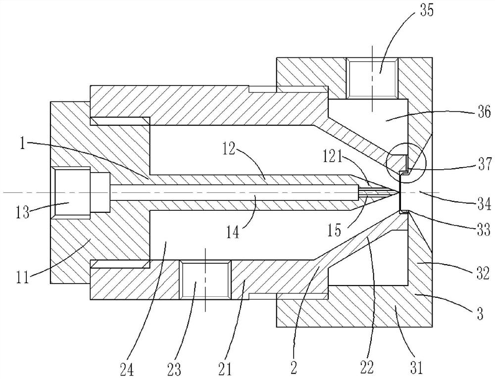
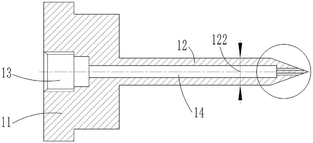
[0052] As shown in the accompanying drawings, an embodiment of the gas-assisted atomizing nozzle of the present invention includes a rear cover body 1, a middle sleeve 2 and a front sleeve 3, and the rear cover body 1 includes a nozzle rear cover 11 and a central liquid pipe 12. The middle sleeve 2 includes a cylindrical section 21 and a cone section 22, and the front sleeve 3 includes a coupling sleeve 31 and a cover plate 32. The nozzle rear cover 11 has a central liquid inlet 13 inside, and the central liquid pipe 12 has a central liquid cavity 14. The central liquid cavity 14 communicates with the external liquid inlet through the central liquid inlet 13. The central liquid pipe 12 It is a tubular structure, the central axis of the central liquid chamber 14 coincides with the central axis of the central liquid pipe 12, the front end 121 of the central liquid pipe is a conical closed structure, and the front end 121 of the central liquid pipe has several central liquid outle...

Embodiment 2

[0083] A nebulizer, the nebulizer includes the gas-assisted atomization nozzle described in Embodiment 1, and thus has the beneficial effects of Embodiment 1, which will not be repeated here.


PUM


Abstract

The gas-assisted atomizing nozzle comprises a rear cover body, a middle sleeve and a front sleeve, an annular air cavity is formed between the middle sleeve and a central liquid pipe, a peripheral liquid cavity is formed between the front sleeve and a conical barrel section, and an inner annular liquid cavity is formed between the tail end of the conical barrel section and the inner surface of a cover plate; compressed air enters the nozzle outlet area through the annular air cavity, liquid enters the nozzle outlet area through the central liquid cavity and the peripheral liquid cavity, and the compressed air and the liquid are mixed and atomized in the nozzle outlet area and are sprayed towards the external space. Through the structural design of the nozzle, liquid forms a multi-liquid-hole axial jet flow and an annular radial jet flow through the two liquid flow channels in the nozzle, and compressed air forms an axial high-speed air flow through the nozzle; the axial high-speed air flow, the multi-liquid-hole axial jet flow and the annular radial jet flow form multi-liquid-hole coaxial mixed atomization and non-coaxial mixed atomization, and therefore the purposes of being large in spray flow, small in fog drop particle size and low in energy consumption are achieved.

Description

technical field [0001] The invention relates to the field of spraying, in particular to a gas-assisted atomizing nozzle and a sprayer thereof. Background technique [0002] Gas-assisted atomizing nozzles and sprayers are widely used in the fields of pesticide spraying, disinfection and drying. Liquids such as pesticides can form fine droplets through the gas-assisted atomizing nozzle. Under the impetus of high-speed airflow, the droplets are deposited on the surface of the object. , can achieve the functions of killing pests, bacteria and so on. In addition, the atomization function of the gas-assisted atomization nozzle can also promote the drying of the solution and achieve the function of spray drying. Gas-assisted atomization nozzle is a nozzle component that uses compressed air to assist liquid atomization. Liquid and compressed air collide and break inside and outside the nozzle, and the liquid produces fine atomization. The sprayer using this nozzle has an atomizatio...

Claims


Application Information

Patent Timeline
IPC IPC(8): B05B7/04B05B1/34
CPCB05B7/0416B05B1/34
Inventor 欧鸣雄胡明朔贾卫东董祥汪明王晓文蒋理
Owner JIANGSU UNIV
Why Eureka
Try Eureka