Industrial robot for injection molding production

A technology for industrial robots and injection pipes, applied in the field of industrial robots, can solve the problems of inconvenient maintenance and operation, port blockage, cooling and hardening, etc., and achieve the effects of improving injection molding stability, reducing blockage, and being less prone to bending and deformation.

Pending Publication Date: 2022-07-08
深圳宗汉曙光科技有限公司
View PDF0 Cites 0 Cited by
  • Summary
  • Abstract
  • Description
  • Claims
  • Application Information

AI Technical Summary

Problems solved by technology

There are mechanical equipment specially used for injection molding. At present, the most commonly used plastics are polyethylene, polypropylene, ABS, PA, polystyrene, etc., and the existing industrial robots use screw propulsion during the injection molding process. Push injection molding, and after the injection is completed, the screw will rotate in reverse to reduce the pressure at the end of the injection tube and prevent the injection material from ejecting during the demoulding process. Therefore, during the injection molding production process, the screw is intermittently positive Inversion requires two processes, and the corresponding parameters need to be input for the servo equipment. In actual use, maintenance and operation are more inconvenient. In addition, the injection plastic at the port is prone to cooling and hardening. Therefore, in the continuous injection molding process, In the case of poor heat control at the port and too long injection intervals, the port is prone to blockage, which brings inconvenience

Method used


Image

  • Industrial robot for injection molding production
  • Industrial robot for injection molding production
  • Industrial robot for injection molding production

Examples


Embodiment Construction

[0029] The following description serves to disclose the invention to enable those skilled in the art to practice the invention. The preferred embodiments described below are given by way of example only, and other obvious modifications will occur to those skilled in the art.

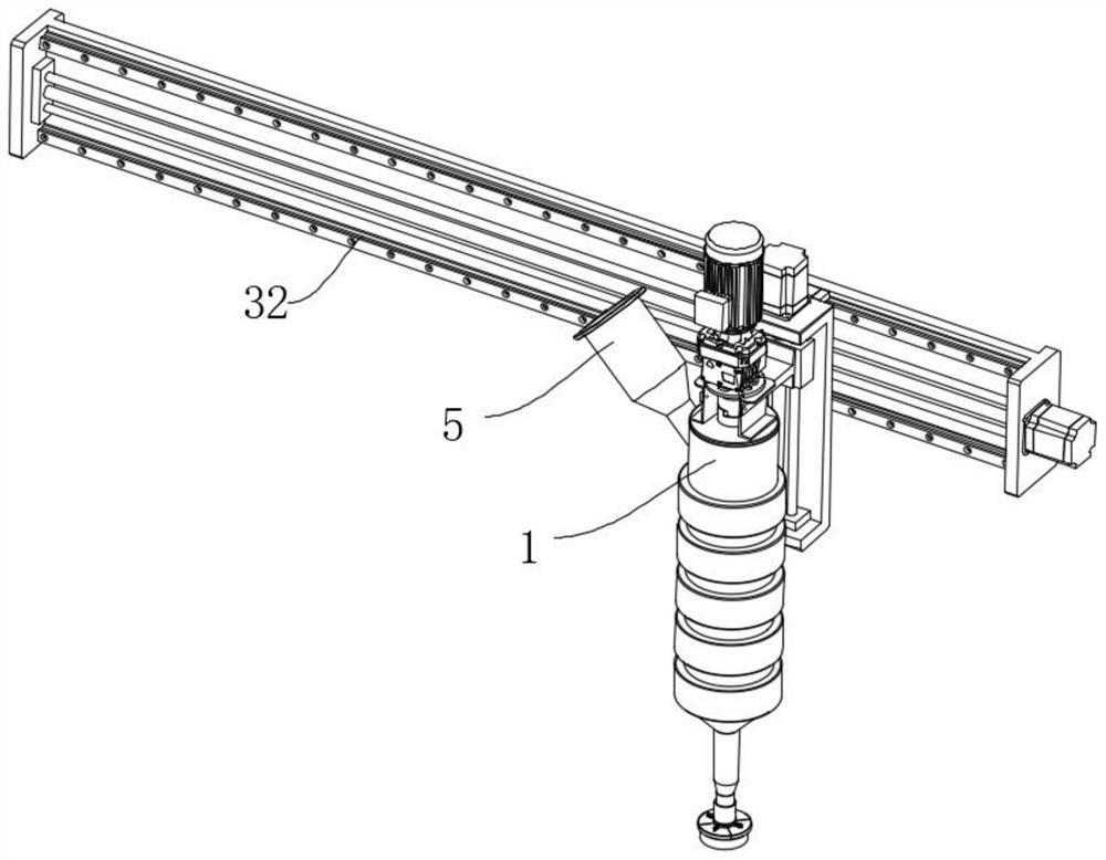
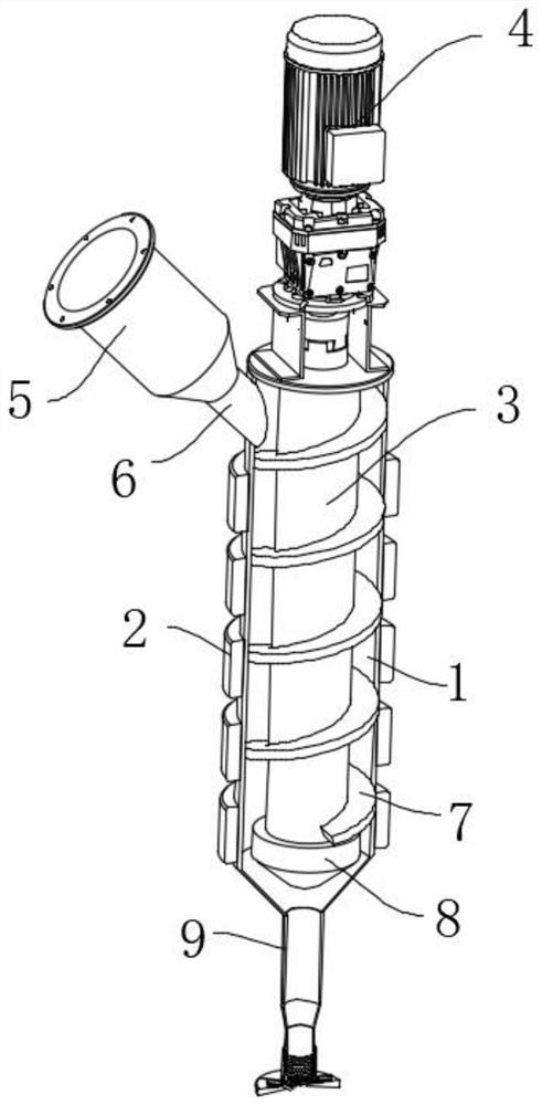
[0030] like Figure 1-Figure 9 The shown industrial robot for injection molding includes a cylinder body 1, the inner side of the cylinder body 1 is provided with a pushing part, the side surface of the cylinder body 1 is provided with a feeding part near the upper end, and the lower end of the cylinder body 1 is provided with a feeding part. The connected injection pipes 10 are provided with a sleeve 11 on the outer surface of the injection pipe 10 near the lower end through an elastic mechanism. And arranged in a circular array, several sealing plates 15 jointly block the lower end of the sleeve 11, a reset mechanism is arranged between the sealing plate 15 and the outer side of the sleeve 11, and the...


PUM


Abstract

The invention relates to the field of industrial robots, in particular to an industrial robot for injection molding production, which comprises a cylinder body, a pushing part is arranged on the inner side of the cylinder body, a feeding part is arranged on the side surface of the cylinder body close to the upper end, and a communicated injection molding pipe is arranged at the lower end of the cylinder body. The mold comprises an injection molding pipe, the position, close to the lower end, of the outer surface of the injection molding pipe is slidably sleeved with a sleeve through an elastic mechanism, the lower end face of the sleeve is provided with a plurality of sealing plates which are in sliding fit with the sleeve, the sealing plates are arranged in an annular array, and the lower end of the sleeve is jointly sealed by the sealing plates. The step of reverse pressure relief after screw propulsion is omitted, the self-plugging function is achieved, meanwhile, molding particles at the end of an injection molding material can be removed during injection molding, the possibility of plugging is effectively reduced, meanwhile, the self-plugging device can be applied to the environment with long adjacent injection molding intervals, the universality is better, and the injection molding stability is improved.

Description

technical field [0001] The invention relates to the field of industrial robots, in particular to an industrial robot for injection molding production. Background technique [0002] Injection molding is a method of producing shapes for industrial products. Products usually use rubber injection molding and plastic injection molding. Plastic injection molding is a method of plastic products. The molten plastic is injected into the mold of plastic products by pressure, and the various plastic parts are obtained by cooling and molding. There are mechanical equipment specially used for injection molding. At present, the most commonly used plastics are polyethylene, polypropylene, ABS, PA, polystyrene, etc., while existing industrial robots use screw propulsion in the process of injection molding. Push the injection molding, and after the injection is completed, the screw will rotate in the opposite direction to reduce the pressure at the end of the injection pipe and prevent the ...

Claims


Application Information

Patent Timeline
Patent Type & Authority Applications(China)
IPC IPC(8): B29C45/17B29C45/20B29C45/27
CPCB29C45/1759B29C45/20B29C45/2737B29C45/278
Inventor 邹迪波巴云辉马琼
Owner 深圳宗汉曙光科技有限公司
Why Eureka
Try Eureka