Plug adopting plastic package terminal component and self-sealing bolt locking power connector

A technology for sealing terminals and plugs, which is applied in the direction of vehicle connectors, clamping/spring connections, connections, etc. It can solve problems such as difficult sealing, loss, and burning of equipment, so as to improve production efficiency, ensure appearance, and meet overall sealing performance Effect

Pending Publication Date: 2019-09-17
CHINA AVIATION OPTICAL-ELECTRICAL TECH CO LTD
View PDF0 Cites 0 Cited by
  • Summary
  • Abstract
  • Description
  • Claims
  • Application Information

AI Technical Summary

Problems solved by technology

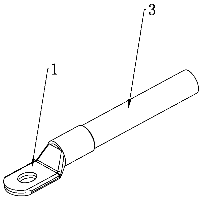
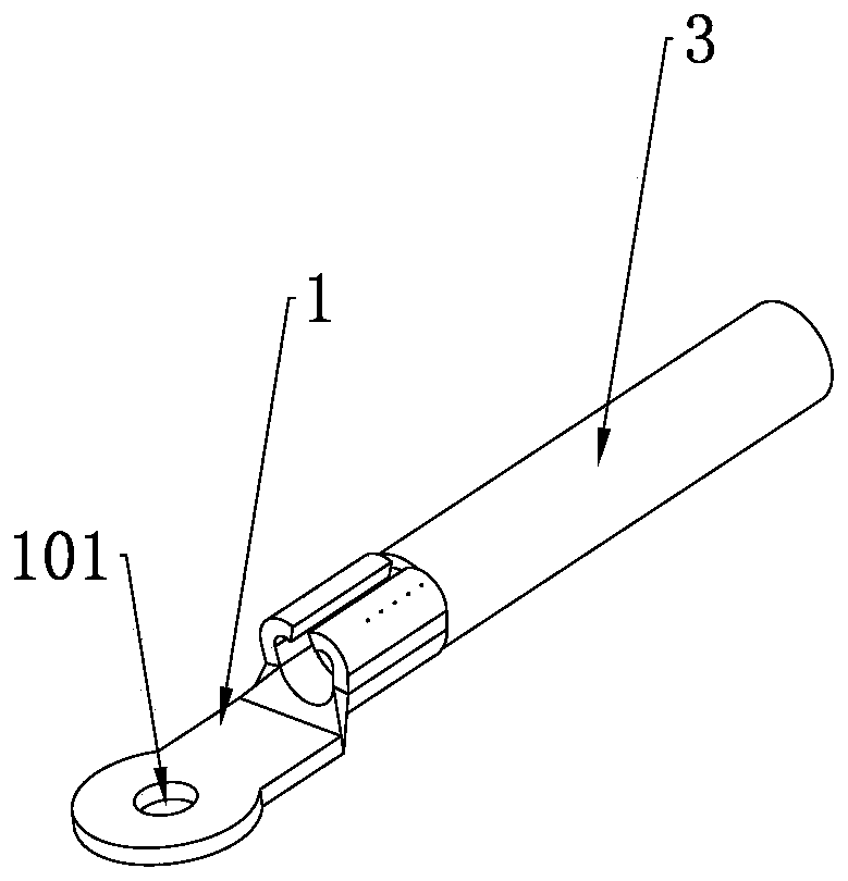
Since the inner core of the cable is generally twisted with multiple strands of copper wire, the inner core of the cable will inevitably be exposed at the crimping or welding position, and it is difficult to design a structure to achieve sealing at this position, and there are tiny gaps in the twisted copper wire itself, so is easily formed as image 3 Leakage channel A shown
In the actual use of the vehicle, if one end of the wiring harness enters water or becomes damp, the water flow or moisture may gradually spread to the other end of the cable along the air leakage channel A, "infecting" and burning the equipment at the other end, causing greater losses

Method used


Image

  • Plug adopting plastic package terminal component and self-sealing bolt locking power connector
  • Plug adopting plastic package terminal component and self-sealing bolt locking power connector
  • Plug adopting plastic package terminal component and self-sealing bolt locking power connector

Examples


Embodiment Construction

[0035] The technical solutions of the present invention will be further described in detail below in conjunction with the accompanying drawings and preferred embodiments. In this embodiment, the position where the plastic-sealed terminal part is located is defined as "front", and the position where the tail button cover is located is defined as "rear".

[0036] see Figure 4 , A plug in this embodiment includes a plastic-sealed terminal part 4 , a straight sleeve 5 , a sealing body 6 , and a tail buckle cover 7 .

[0037] see Figure 5 and Image 6 , the plastic-sealed terminal component 4 is an integrated component formed by plastic-sealing the terminal 1 alone, including the terminal 1 and the first plastic-sealed housing 401 formed by plastic-sealing the terminal. In this embodiment, only the terminal is plastic-sealed, and the terminal The connected cables are not plastic-encapsulated, which can eliminate the risk of plastic-encapsulated wires. The first plastic casing...


PUM


Abstract

The invention provides a plug adopting a plastic package terminal component. The plastic package terminal component comprises a terminal and a first plastic package shell body which is formed by carrying out plastic package on the terminal. The first plastic package shell body is provided with a cavity, wherein a conductive stud on a socket matched with the plug can be inserted into the cavity to be connected with the terminal. The end part, for insertion of the conductive stud, of the first plastic package shell body is provided with a second sealing ring for sealing an inserting surface of the plug and the socket. The end part of the terminal is positioned in the cavity, and the other end part of the terminal protrudes out of the first plastic package shell body. The first plastic package shell is detachably connected with a sealing component through a locking mechanism, and the sealing component is provided with a closed cavity which allows a cable to penetrate through to be connected with the other end of the terminal and can accommodate the terminating position of the cable and the terminal. The plug only conducts plastic package on the terminals independently, the terminating positions of the terminals and the cable are contained in the closed cavity of the sealing component, so an air leakage channel is eliminated, and a self-sealing function is achieved.

Description

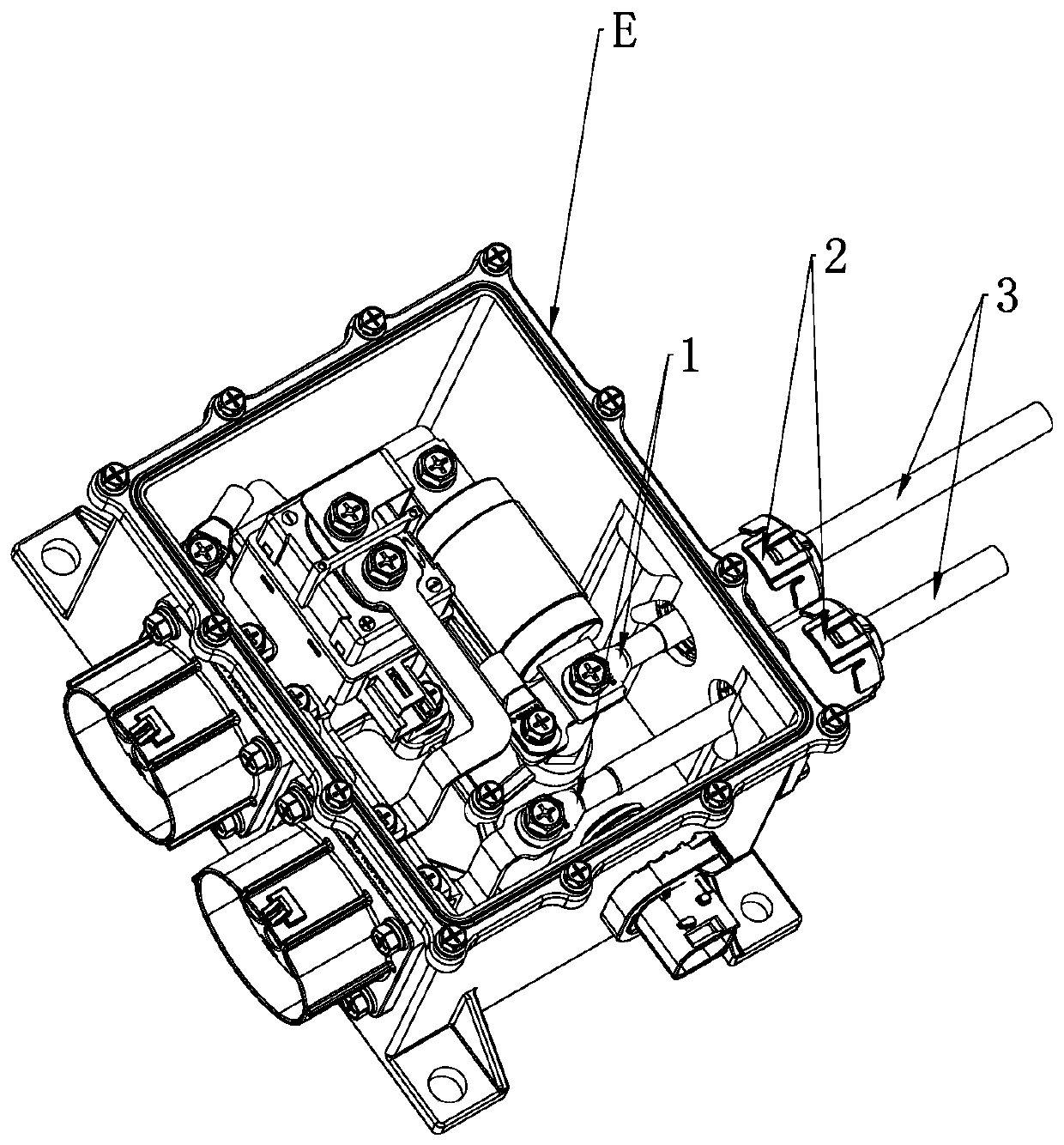
technical field [0001] The invention belongs to the technical field of automotive connectors, and in particular relates to a plug and a self-sealing bolt locking power connector using plastic-sealed terminal parts. Background technique [0002] With the rapid development of the new energy automobile industry, the high voltage and high current (25mm 2 and above cable specifications) the safety requirements of components are getting higher and higher. see figure 1 At present, the commonly used connector structure is to lock the terminal 1 of the power connector and the copper bar inside the equipment E through bolts to realize power transmission. With the advantages of high vibration performance and convenient assembly and operation, it is widely used in vibration source components such as motor power, controllers, and reducers. For this type of power connector, the gap between the housing of the connector itself and the housing of the device is generally filled with rubber...

Claims


Application Information

Patent Timeline
IPC IPC(8): H01R13/52H01R13/506H01R13/502H01R4/30
CPCH01R13/5202H01R13/5205H01R13/5219H01R13/506H01R13/502H01R4/30H01R2201/26
Inventor 郑文杰牛冬冬白光辉
Owner CHINA AVIATION OPTICAL-ELECTRICAL TECH CO LTD
Why Eureka
Try Eureka