
Moving sidewalk with foot protecting and falling preventing functions

A moving walkway and anti-fall technology, applied in escalators, transportation and packaging, etc., can solve problems such as falls, and achieve the effects of prolonging service life, reducing contact area, and reducing friction

Pending Publication Date: 2022-07-08
SPECIAL EQUIP SAFETY SUPERVISION INSPECTION INST OF JIANGSU PROVINCE
View PDF0 Cites 0 Cited by
  • Summary
  • Abstract
  • Description
  • Claims
  • Application Information

AI Technical Summary

Problems solved by technology

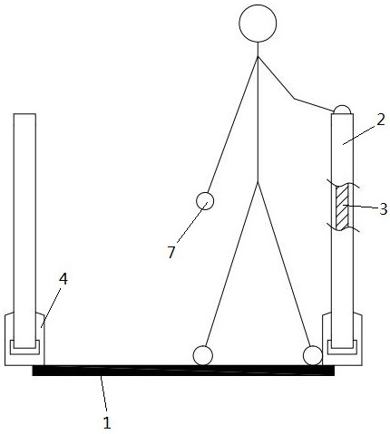
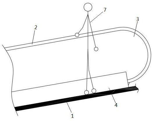
Since the passenger moves with the handrail and the aisle, the skirt is still, and the shoes and the skirt board have relative motion, the friction generated when the outer side of the shoe contacts the skirt board surface will drag the foot backward, especially if it is made of rubber, silicone, plastic, etc. The backward friction generated when the side of the non-slip sole is in contact with the smooth metal skirt on the second surface can easily cause people to fall

Method used


Image

  • Moving sidewalk with foot protecting and falling preventing functions
  • Moving sidewalk with foot protecting and falling preventing functions
  • Moving sidewalk with foot protecting and falling preventing functions

Examples


Embodiment 1

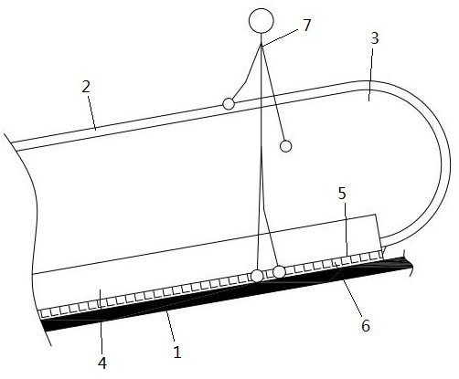
[0029] Example 1: as Figures 3 to 6 As shown in the figure, a moving walk with foot protection and anti-fall function includes a walkway 1, a handrail 2, a glass guard plate 3 and a skirt plate 4, the walkway 1 is located between the bottoms of the two skirt plates 4, and the glass guard plate 3 is connected to The top of the skirt plate 4, the handrail 2 is slidably connected to the top of the glass guard plate 3; the inner bottom of the two skirt plates 4 is connected with a fixing strip 5, and the fixing strip 5 and the inner surface are connected with a number of brushes 6, and the hair The direction of the brush 6 is the same as that of the aisle 1; the fixing strip 5 is connected to the inner side of the apron 4 through screws, the brush 6 is detachably connected to the inner side of the fixing strip 5, and the brush 6 is perpendicular to the aisle 1; The brush 6 includes bristles 601 and a base 602. The front end of the base 602 is provided with a slot, and the bristle...

Embodiment 2

[0030] Embodiment 2: This embodiment is a further improvement of Embodiment 1. The main improvement is that when Embodiment 1 is in use, the bristles 601 and the previous base 602 have a higher resistance when squeezed; , can avoid the above defects, specifically:

[0031] The upper part of the rear side of the base 602 is an arc-shaped slope 604 with a smooth transition; the arc-shaped slope 604 is provided with a plurality of grooves 605; in this embodiment, the upper part of the rear side of the base 602 is an arc-shaped transition with a smooth transition Slope 604 to reduce the resistance of the shoes rubbing from here; at the same time, the arc-shaped slope 604 can also prevent the bristles 601 from being cut at right angles, thereby prolonging the service life of the bristles 601; the arc-shaped slope 604 is provided with a number of grooves 605, when the shoes When rubbing against the bristles 601 , the bristles 601 are partially squeezed into the groove and subjected ...


PUM


Abstract

The invention discloses a moving sidewalk with foot protection and fall prevention functions, which comprises a walkway, a hand strap, a glass protection plate and apron boards, the walkway is located between the bottoms of the two apron boards, the glass protection plate is connected to the top of the apron boards, and the hand strap is slidably connected to the top of the glass protection plate; the bottoms of the inner sides of the two apron boards are connected with fixing strips, the fixing strips and the inner side faces are connected with a plurality of brushes, and the direction of the brushes is the same as the trend of the walkway. The fixing strips are connected to the inner sides of the apron boards through screws, the brushes are detachably connected to the inner side faces of the fixing strips, and the brushes are perpendicular to the walkway. The brush comprises bristles and a base, an inserting groove is formed in the front end of the base, and the bristles are sequentially bonded in the inserting groove. The bristles are arranged on the apron board of the moving sidewalk, so that friction force between shoes of passengers and the apron board is reduced, and accidents caused by stumbling of the passengers are avoided.

Description

technical field [0001] The invention relates to the technical field of moving walks, in particular to a moving walk with foot protection and anti-fall function. Background technique [0002] Moving walks refer to fixed electric drive equipment with circulating running (slab or belt) walkways used for transporting passengers with a horizontal or inclined angle of not more than 12°. Moving walks are suitable for places where people are concentrated, such as stations, docks, shopping malls, airports, exhibition halls and stadiums. Appeared in the early 20th century. The structure is similar to the escalator, mainly composed of two parts: movable road surface and handrail. Usually, its active road surface does not form steps when it is inclined. [0003] like figure 1 , 2 As shown, when the passenger rides the moving sidewalk, one hand holds the handrail, and the outer side of the shoe on the same side easily contacts the skirt. Since the passenger moves with the handrail ...

Claims


Application Information

Patent Timeline
Patent Type & Authority Applications(China)
IPC IPC(8): B66B23/22B66B29/04
CPCB66B23/22B66B29/04
Inventor 黄梓庭张士星刘鑫袁仁杰
Owner SPECIAL EQUIP SAFETY SUPERVISION INSPECTION INST OF JIANGSU PROVINCE
Learn More