
Rapid installation method for large cone steel structure in narrow space

An installation method and technology of vertebral body steel, which are applied in building construction, construction material processing, construction, etc., can solve the problems of long welding operation time, uneconomical, long crane time, etc., so as to improve installation efficiency and improve assembly. The effect of efficiency

Pending Publication Date: 2022-07-08
CHINA FIRST METALLURGICAL GROUP +1
View PDF6 Cites 0 Cited by
  • Summary
  • Abstract
  • Description
  • Claims
  • Application Information

AI Technical Summary

Problems solved by technology

[0003] In the related technology, the on-site assembly method is to assemble the large-scale vertebral steel structure with the large-caliber mouth facing down. The component assembly needs to occupy a large area, and the welding operation time during assembly is long, and the site is temporarily occupied for a long time. After the structure is assembled, it is necessary to turn over the large vertebral steel structure for installation during hoisting and installation, which is very dangerous, and the construction work in a narrow space blocks road traffic
And the height of the large vertebral body is as high as 15-16 meters, so the scaffolding needs to be set up during the assembly and welding process, and the high-altitude operation has a high risk factor and is unsafe
And after the assembly is completed, the weight of the large-scale vertebral steel structure reaches 50-60 tons, requiring a crane with a large rated load to cooperate with the installation, and the cost of a large crane is high
It takes a long time to install and use the crane, which is uneconomical and hinders traffic

Method used


Image

  • Rapid installation method for large cone steel structure in narrow space
  • Rapid installation method for large cone steel structure in narrow space
  • Rapid installation method for large cone steel structure in narrow space

Examples


Embodiment Construction

[0030] The technical solutions in the embodiments of the present application will be clearly and completely described below with reference to the accompanying drawings in the embodiments of the present application. Obviously, the described embodiments are only a part of the embodiments of the present application, but not all of the embodiments. Based on the embodiments in the present application, all other embodiments obtained by those skilled in the art without creative work fall within the protection scope of the present application.

[0031] In the description of this application, it should be understood that the terms "first" and "second" are only used for description purposes, and cannot be interpreted as indicating or implying relative importance or implicitly indicating the number of indicated technical features. Thus, features defined as "first", "second" may expressly or implicitly include one or more of said features. In the description of the present application, "...


PUM


Abstract

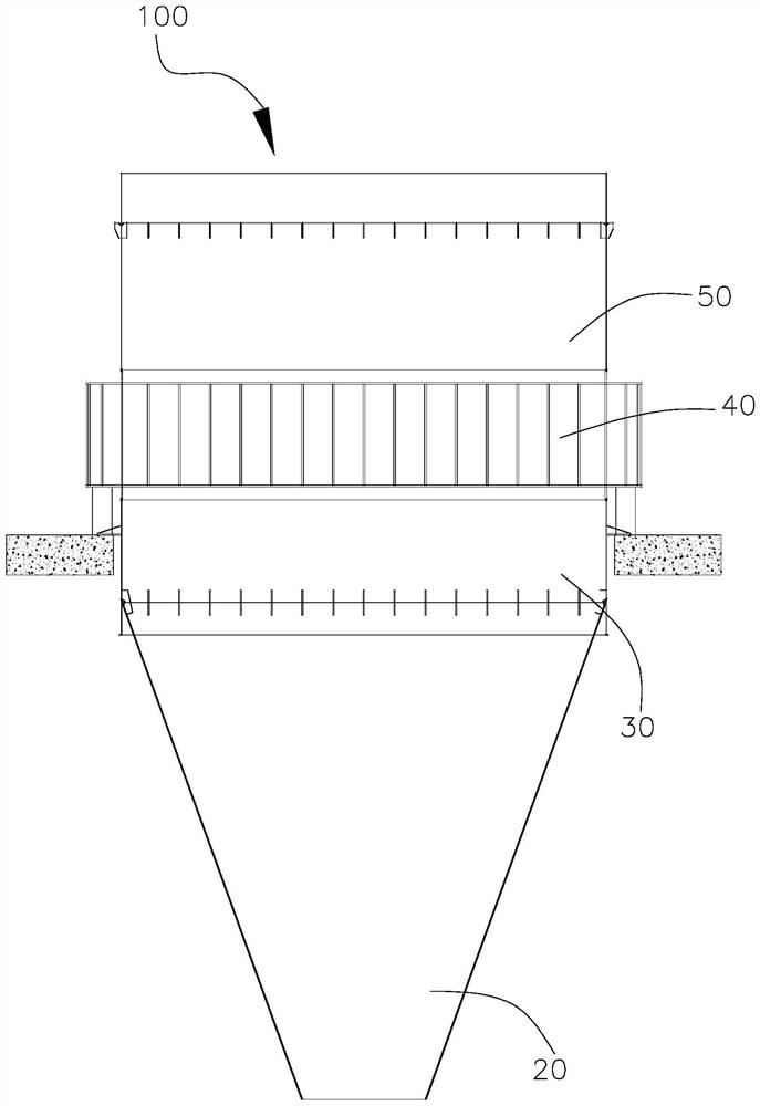
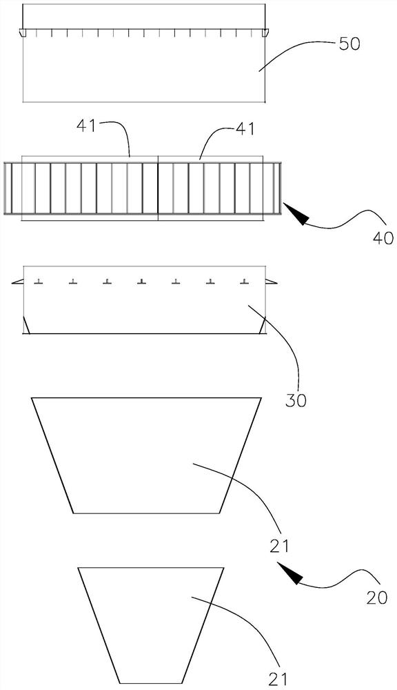
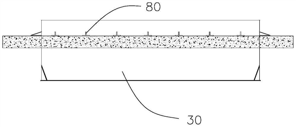
The invention discloses a rapid installation method for a large cone steel structure in a narrow space. According to the technical scheme, when installation operation is carried out, firstly, a target cone steel structure is divided into a bottom section, a positioning and supporting section, a ring beam section and a top section according to the installation sequence from bottom to top, and then the positioning and supporting section, the ring beam section, the top section and the bottom section are sequentially installed at the designated positions. Due to the adoption of segmented assembly, not only is the assembly efficiency improved, but also the problems of high danger coefficient, inconvenience and limited field of hoisting which adopts integral assembly and then is mounted in the prior art are solved. In addition, due to the fact that the positioning supporting section with the installation position in the middle is firstly installed, and then the other sections are installed from the two end faces of the positioning supporting section, installation can be conducted without waiting for all the components to be in order, line production is formed, the large cone steel structure can be directly installed after arriving at the site, and the installation efficiency is improved.

Description

technical field [0001] The present application relates to the technical field of steel structure installation, and in particular, to a rapid installation method of a large-scale vertebral steel structure in a narrow space. Background technique [0002] Aiming at the rapid installation method of large-scale vertebral steel structure in narrow space, it is mainly used in the renovation and expansion of smelting and construction projects. The steel structure system is adjacent to various original buildings for construction and installation. The construction site is not only narrow, but also the surrounding various steel-making work systems are intricate , Unreasonable installation method seriously affects road traffic. For the above reasons, it is difficult to install a large-scale vertebral steel structure system. The rapid installation method of large-scale vertebral steel structure in narrow space, according to the structural characteristics of the project, determines the d...

Claims


Application Information

Patent Timeline
Patent Type & Authority Applications(China)
IPC IPC(8): E04G21/14E04B1/38
CPCE04G21/14E04B1/38
Inventor 杨晓建曾强国庞宗富周明广古纳唐文娜
Owner CHINA FIRST METALLURGICAL GROUP
Learn More