Rotor punching sheet, motor rotor and motor

A rotor punching and punching technology is applied in the field of permanent magnet synchronous motor devices, which can solve the problems of high cost, increase motor torque ripple and noise, etc., and achieve the effects of weakening vibration noise and reducing vibration amplitude.

Pending Publication Date: 2022-07-08
SHANGHAI HITACHI ELECTRICAL APPLIANCES CO LTD
View PDF0 Cites 0 Cited by
  • Summary
  • Abstract
  • Description
  • Claims
  • Application Information

AI Technical Summary

Problems solved by technology

[0005] The purpose of the present invention is to provide a rotor punch, a motor rotor and a motor to solve the problem of high motor material cost in the prior art, and redu

Method used


Image

  • Rotor punching sheet, motor rotor and motor
  • Rotor punching sheet, motor rotor and motor
  • Rotor punching sheet, motor rotor and motor

Examples


Embodiment Construction

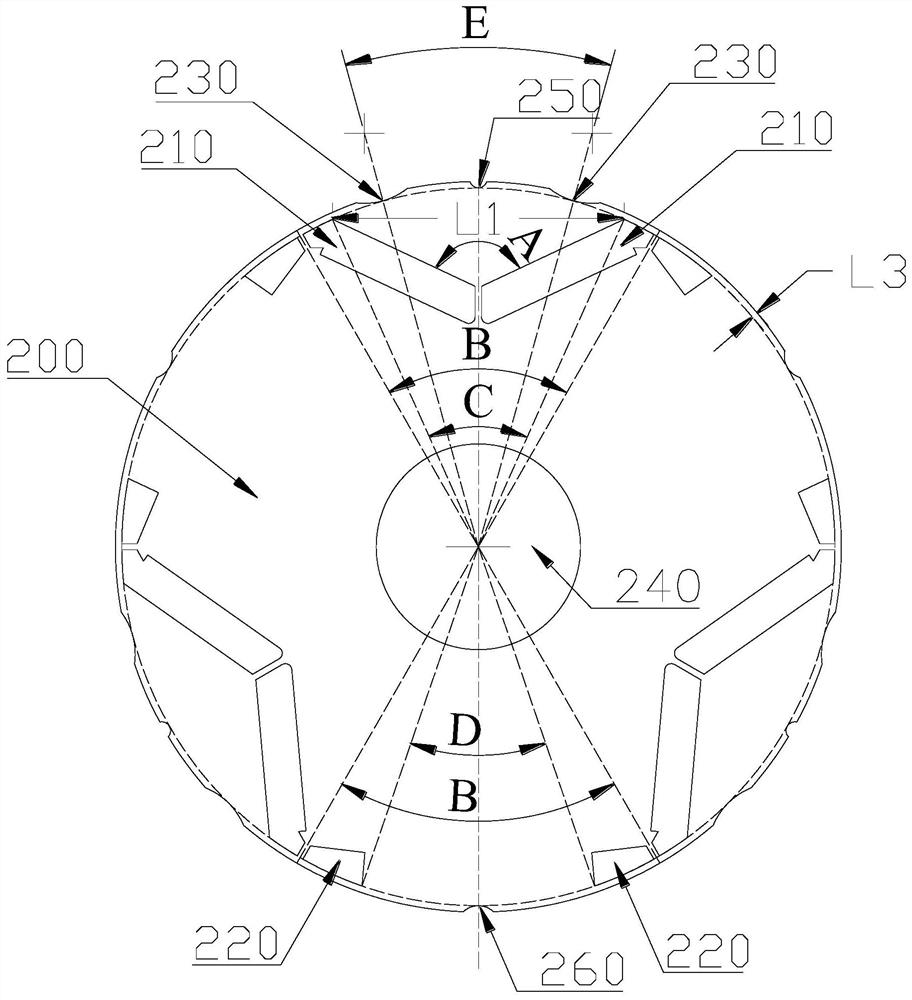
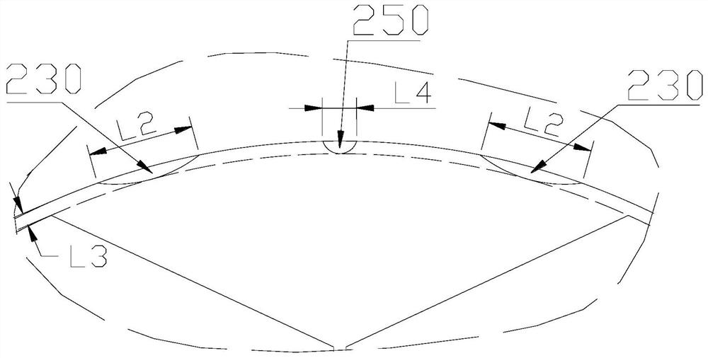
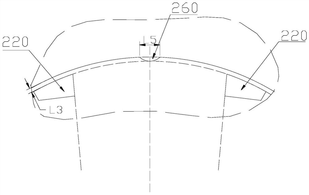
[0047] In order to make the objects, advantages and features of the present invention clearer, the following combination Figure 1 to Figure 8 The rotor punching sheet, the motor rotor and the motor proposed by the present invention are further described in detail. It should be noted that the accompanying drawings are in a very simplified form and use inaccurate scales, and are only used to facilitate and clearly assist the purpose of illustrating the embodiments of the present invention, and are not intended to limit the conditions for the implementation of the present invention, so they are not technically The substantive meaning, any modification of the structure, the change of the proportional relationship or the adjustment of the size, without affecting the effect that the present invention can produce and the purpose that can be achieved, should still fall within the technical content disclosed in the present invention. within the scope of coverage.

[0048] It should b...


PUM


Abstract

The invention provides a rotor punching sheet, a motor rotor and a motor, the rotor punching sheet comprises a punching sheet body, and the punching sheet body is uniformly provided with an odd number of magnetic poles along the circumferential direction; each magnetic pole comprises two magnetic steel grooves which are distributed in a V shape; two first air gap grooves and two auxiliary grooves which are in one-to-one correspondence with the two magnetic steel grooves of the magnetic poles are formed in the positions, corresponding to the magnetic poles, of the edge of the outer circle of the punching sheet body, and the first air gap grooves are located in an area defined by the two magnetic steel grooves of the magnetic poles; the auxiliary groove is located outside an area enclosed by the two magnetic steel grooves of the magnetic pole. The motor rotor comprises the rotor punching sheet. The motor comprises the motor rotor. According to the rotor punching sheet provided by the invention, the motor material cost can be effectively reduced by 20%, the operation efficiency of the motor is ensured, and the noise level of the rotor punching sheet is basically consistent with that of a traditional motor.

Description

technical field [0001] The invention relates to the technical field of permanent magnet synchronous motor devices, in particular to a rotor punch, a motor rotor and a motor. Background technique [0002] In recent years, motor technology, especially permanent magnet synchronous motor technology, has developed rapidly, and the design of motor body structure is becoming more and more novel. In addition to its performance, the material cost of motor products also determines whether the motor can be finally introduced to the market. [0003] Generally, the motor includes a stator and a rotor, a wire group is wound on the stator, the rotor extends into the stator, and the rotor includes a rotor shaft and a plurality of stacked rotor punches installed on the rotor shaft, each of which is opened on the rotor punch. There are magnetic steel slots, and the magnets are embedded in the corresponding magnetic steel slots of all the rotor punching pieces, so as to form electromagnetic ex...

Claims


Application Information

Patent Timeline
IPC IPC(8): H02K1/276H02K21/02H02K21/14
CPCH02K1/2766H02K21/028H02K21/14H02K2201/03H02K2213/03Y02T10/64
Inventor 张耀汪圣原范杰
Owner SHANGHAI HITACHI ELECTRICAL APPLIANCES CO LTD
Why Eureka
Try Eureka