Gas sealing structure and extraction drying device

A technology of gas sealing and structure, applied in the direction of progressive dryer, engine sealing, drying, etc., can solve the problems of large-scale equipment and increased cost, and achieve the effect of ensuring airtightness

Pending Publication Date: 2022-07-08
SHIBAURA MASCH CO LTD
View PDF15 Cites 0 Cited by
  • Summary
  • Abstract
  • Description
  • Claims
  • Application Information

AI Technical Summary

Problems solved by technology

However, in this case, the sheet-like member conveyed from the processing chamber is conveyed outside the processing chamber after passing through water, so after being sent out from the p...

Method used


Image

  • Gas sealing structure and extraction drying device
  • Gas sealing structure and extraction drying device
  • Gas sealing structure and extraction drying device

Examples


Embodiment approach 1

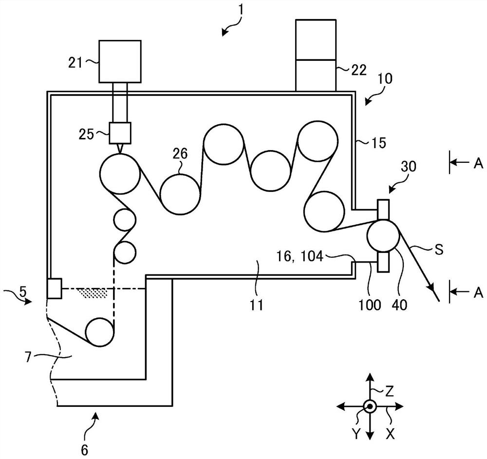
[0041] figure 1 It is a schematic diagram which shows the apparatus structure of the extraction-drying apparatus 1 concerning Embodiment 1. In addition, in the following description, the up-down direction in the normal use state of the extraction-drying apparatus 1 is demonstrated as the up-down direction Z of the extraction-drying apparatus 1, and the upper side in the normal use state of the extraction-drying apparatus 1 is demonstrated. The upper side of the extraction and drying apparatus 1 and the lower side in a normal use state of the extraction and drying apparatus 1 will be described as the lower side of the extraction and drying apparatus 1 . In addition, the horizontal direction in the normal use state of the extraction-drying apparatus 1 is demonstrated as a horizontal direction also in the extraction-drying apparatus 1. FIG. Furthermore, in the horizontal direction, the extending direction of the sealing roller 40 of the gas sealing structure 30 described later i...


PUM


Abstract

In order to easily ensure sealing properties, a gas sealing structure (30) is provided with: a sealing roller (40) which divides a drying chamber (11) and is disposed on the surface side opposite to the surface on the drying chamber (11) side of a partition wall (15) having an opening (16) through which a sheet-like member (S) passes; a conveyance section labyrinth seal (60) that is disposed at a position facing the outer peripheral surface (41) of the seal roller (40), that allows the sheet member (S) conveyed from the opening (16) to pass through to a position between the conveyance section labyrinth seal (60) and the seal roller (40), and that has a plurality of space sections (67) that are arranged in the conveyance direction of the sheet member (S) and that are open on the seal roller (40) side; and an exhaust duct (22) that causes the inside of the drying chamber (11) to have negative pressure with respect to the side where the seal roller (40) is disposed.

Description

technical field [0001] The present invention relates to a gas sealing structure and an extraction and drying apparatus. Background technique [0002] A manufacturing apparatus for forming a sheet-like member of a resin film generally has a plurality of processing steps, and the sheet-like member is formed through each processing step. However, in the processing step at the time of forming, the sheet-like member is conveyed from a processing chamber In some cases, it may be necessary to convey the sheet-like member while suppressing outflow of gas from the processing chamber. As one method for conveying the sheet-like member while securing the airtightness and suppressing the outflow of gas, it is conceivable to arrange a tank filled with water at the outlet of the processing chamber, and to immerse the outlet of the processing chamber in water to suppress the gas The method of outflow from the processing chamber. However, in this case, the sheet-like member transported fro...

Claims


Application Information

Patent Timeline
IPC IPC(8): F27D7/06
CPCF16J15/447F27D7/06F26B3/04F26B13/14F26B13/005F26B25/008F27B9/145F27B9/045C21D9/561C21D9/565F16J15/16F26B13/00F27B9/04
Inventor 结城拓哉佐野孝义
Owner SHIBAURA MASCH CO LTD
Why Eureka
Try Eureka