
Underwater glider towing test wing rudder angle transformation structure

An underwater glider and wing technology, which is applied to underwater ships, underwater operation equipment, motor vehicles, etc., can solve the problem that the change of the rudder angle of the trailing edge of the wing of the underwater glider cannot be realized, and the interior space of the wing is narrow and difficult to place. Servo and other problems, to achieve the effect of simple and convenient replacement, low cost and easy maintenance

Pending Publication Date: 2022-07-12
NORTHWESTERN POLYTECHNICAL UNIV
View PDF0 Cites 0 Cited by
  • Summary
  • Abstract
  • Description
  • Claims
  • Application Information

AI Technical Summary

Problems solved by technology

However, the rudder surface of the aircraft is generally located at the trailing edge of the wing surface, where the space inside the wing is narrow, and the general rudder surface control mechanism must ensure that there are no exposed parts and not destroy the original aerodynamic shape of the aircraft, which is difficult to achieve.
[0006] In the underwater glider scale model experiment, the scale ratio is 1:5, and the wing thickness of the scaled glider is only about 10mm. To ensure the original hydrodynamic shape, it is difficult to place the rudder in such a small space Therefore, according to the existing technology, it is impossible to achieve the purpose that the rudder angle of the trailing edge of the wing of the underwater glider can be changed within a certain range.

Method used


Image

  • Underwater glider towing test wing rudder angle transformation structure
  • Underwater glider towing test wing rudder angle transformation structure
  • Underwater glider towing test wing rudder angle transformation structure

Examples


Embodiment Construction

[0028] The embodiments described below with reference to the accompanying drawings are exemplary, and are intended to explain the present invention and should not be construed as limiting the present invention.

[0029] In the description of the present invention, it should be understood that the terms "center", "longitudinal", "lateral", "length", "width", "thickness", "upper", "lower", "front", " rear, left, right, vertical, horizontal, top, bottom, inside, outside, clockwise, counterclockwise, etc., or The positional relationship is based on the orientation or positional relationship shown in the accompanying drawings, which is only for the convenience of describing the present invention and simplifying the description, rather than indicating or implying that the referred device or element must have a specific orientation, be constructed and operated in a specific orientation, Therefore, it should not be construed as a limitation of the present invention.

[0030] figure ...


PUM


Abstract

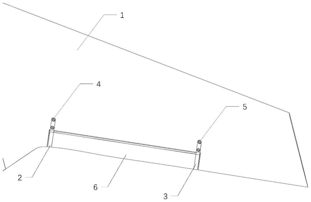
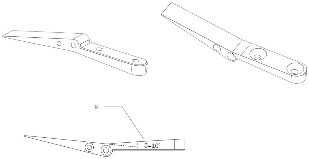
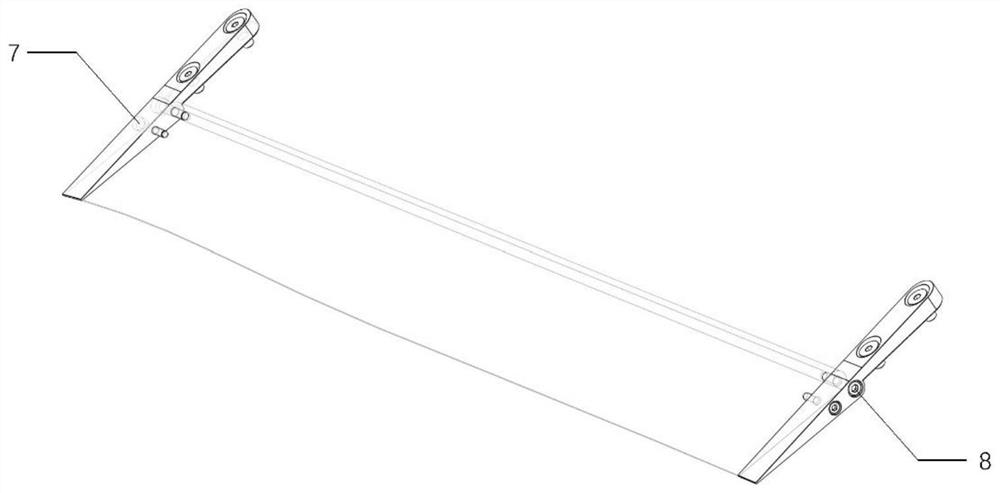
The invention discloses a wing rudder angle transformation structure for an underwater glider towing test, and belongs to the field of hydrodynamic experiments. Comprising a rudder plate, a left angle piece and a right angle piece, and the two sides of the rudder plate are fixed to the middle section of the rear edge of a wing through the left angle piece and the right angle piece respectively; the left angle piece is a strip-shaped plate with an included angle, the front half section of the left angle piece is fixedly mounted in a mounting groove in the surface of the wing, the upper surface is flush with the surface of the wing, and the rear half section is fixed to the left side of the rudder plate; an acute included angle between the front half section and the rear half section of the left angle sheet is a rudder angle; the right angle piece and the left angle piece are of a symmetrical structure. According to the invention, through the ingenious adaptive design of the angle sheet, the connection surfaces of the angle sheet and the wing and the rudder plate are conformal, the original hydrodynamic characteristics of the angle sheet can be maintained during an experiment, and the measured data are more accurate and real. By adopting the thought of replacing the angle piece, a steering engine with a complex structure is prevented from being used.

Description

technical field [0001] The invention belongs to the field of hydrodynamic experiments, and in particular relates to a wing rudder angle conversion structure of an underwater glider dragging test. Background technique [0002] As a tool for exploring and developing the ocean, underwater vehicle plays an important role in the process of human exploration of the ocean. It is more and more obvious and has broad application prospects. [0003] Automatic Underwater Glider, AUG, as a new type of underwater robot, requires little energy, so it can sail in the ocean for a long time with high efficiency. Although the underwater glider is not as fast as other autonomous underwater vehicles, the advantages of low cost and low maintenance make it an underwater vehicle that is widely used in ocean monitoring, and because it can be reused and a large number of Dropped, underwater gliders play an important role in large-scale ocean exploration. The basic working principle of an underwate...

Claims


Application Information

Patent Timeline
IPC IPC(8): B63G8/18B63B71/00
CPCB63G8/18B63B71/00B63G2008/002Y02T70/10
Inventor 施瑶潘光宋东黄桥高杜晓旭姜军赵海瑞
Owner NORTHWESTERN POLYTECHNICAL UNIV
Learn More