Low-temperature liquid underground ice hole energy storage device and method

A low-temperature liquid, energy storage device technology, used in gas/liquid distribution and storage, geothermal power generation, greenhouse gas reduction, etc., can solve the problems of low energy density, high manufacturing cost, limited monomer volume, etc., to prevent volatilization The effect of leakage, improved sealing, and cost reduction

Pending Publication Date: 2022-07-12
中山先进低温技术研究院 +1
View PDF14 Cites 0 Cited by
  • Summary
  • Abstract
  • Description
  • Claims
  • Application Information

AI Technical Summary

Problems solved by technology

However, in my country, the areas where renewable energy abandonment is concentrated and the areas with salt caverns suitable for large-scale underground hydrogen energy storage do not overlap geographically, which makes it difficult to implement this ideal energy storage method.
[0004] In addition, the current renewable energy electrolysis water hydrogen production mainly uses gaseous hydrogen as the energy storage medium, the energy density of the energy storage is low, and the high-pressure hydrogen needs special tanks for shipment, and the current manufacturing cost of special storage tanks is relatively high And the volume of the monomer is limited, resulting in high storage and transportation costs of hydrogen, and high hydrogen costs for end users
[0005] In the existing aerospace industry, liquid hydrogen storage tanks are mostly used for liquid hydrogen storage, and there are strict requirements on the daily evaporation rate of liquid hydrogen. Complex low-temperature insulation structures and materials are used, which lead to high manufacturing costs and low ground storage safety. The density is higher than that of gaseous hydrogen, but the storage volume is still limited. The maximum can only be a few thousand cubic meters, and it is difficult to achieve large-scale storage of tens of thousands or even hundreds of thousands of cubic meters

Method used


Image

  • Low-temperature liquid underground ice hole energy storage device and method

Examples


Embodiment Construction

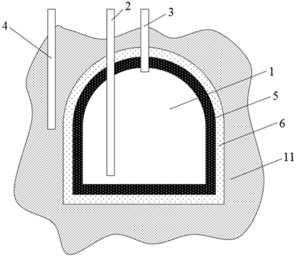
[0034] To make the purposes, technical solutions and advantages of the embodiments of the present invention clearer, the technical solutions in the embodiments of the present invention will be described clearly and completely below with reference to the accompanying drawings in the embodiments of the present invention. Obviously, the described embodiments are some, but not all, embodiments of the present invention. The components of the embodiments of the invention generally described and illustrated in the drawings herein may be arranged and designed in a variety of different configurations.

[0035] The technical solutions in the embodiments of the present invention will be clearly and completely described below in conjunction with the embodiments of the present invention. Obviously, the described embodiments are only a part of the embodiments of the present invention, but not all of the embodiments. Based on the embodiments of the present invention, all other embodiments ob...


PUM

PropertyMeasurementUnit
Bulk densityaaaaaaaaaa

Abstract

The invention provides a low-temperature liquid underground ice hole energy storage device and method. The low-temperature liquid underground ice hole energy storage device comprises a storage hole, a first pipeline, a second pipeline and a water injection pipe. Low-temperature liquid is introduced into the storage cavity through a first pipeline; water is introduced into the outer wall of the storage cavity through the water injection pipe, under the low-temperature action of the low-temperature liquid, the water in the outer wall of the storage cavity is frozen into ice, the outer wall of the storage cavity can be frozen into a frozen soil layer, the sealing performance of a geological layer is improved, the low-temperature liquid can be prevented from volatilizing and leaking, and then the low-temperature liquid is effectively stored; compared with a high-cost vacuum heat insulation layer and a high-cost accumulation heat insulation layer of an existing small and medium-sized low-temperature liquid storage tank, the underground ice hole energy storage device has the advantages that a natural heat insulation layer and a compact ice hole are formed through a deep and thick geological layer of hundreds of meters to thousands of meters for heat insulation, and the cost of a low-temperature liquid storage system is greatly reduced.

Description

technical field [0001] The invention relates to the technical field of cryogenic liquid storage, in particular to a cryogenic liquid underground ice cave energy storage device and method. Background technique [0002] Renewable energy power generation, such as wind power, photovoltaic power generation, hydropower generation, etc., has the characteristics of seasonality, volatility, discontinuity, etc., resulting in a large amount of electricity curtailment in my country's renewable energy power generation; only in the first quarter of 2021 , the total amount of electricity abandoned in my country's renewable energy power generation exceeds 10 billion kWh. Large-scale energy storage technology can be used to absorb and regenerate the abandoned electricity of renewable energy, and make full use of this part of renewable energy to further reduce carbon emissions and optimize the energy use structure. [0003] The consumption of abandoned electricity from renewable energy throug...

Claims


Application Information

Patent Timeline
IPC IPC(8): F17C1/12F17C13/08
CPCF17C1/12F17C13/081F17C2201/01F17C2203/0341F17C2203/037F17C2221/012F17C2223/013Y02E70/30
Inventor 龚领会王倩周涵贺明吕翠
Owner 中山先进低温技术研究院
Why Eureka
Try Eureka