Bone joint correcting device capable of being changed into kneecap by increasing or decreasing structure

A technology of bone joints and knee pads, applied in the field of medical care, can solve problems such as undiscovered technologies and patents

Pending Publication Date: 2022-07-15
AIR FORCE MEDICAL UNIV
View PDF0 Cites 0 Cited by
  • Summary
  • Abstract
  • Description
  • Claims
  • Application Information

AI Technical Summary

Problems solved by technology

[0006] Searched the public database of Chinese patents with the keywords "corre

Method used


Image

  • Bone joint correcting device capable of being changed into kneecap by increasing or decreasing structure
  • Bone joint correcting device capable of being changed into kneecap by increasing or decreasing structure
  • Bone joint correcting device capable of being changed into kneecap by increasing or decreasing structure

Examples


Embodiment 1

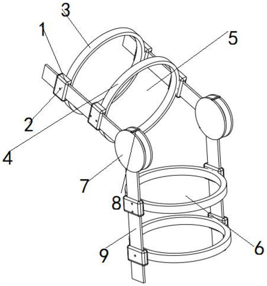
[0044] Example 1: Combining figure 1 and figure 2 The bone joint correction device whose structure can be increased or decreased to become a knee brace is characterized in that:

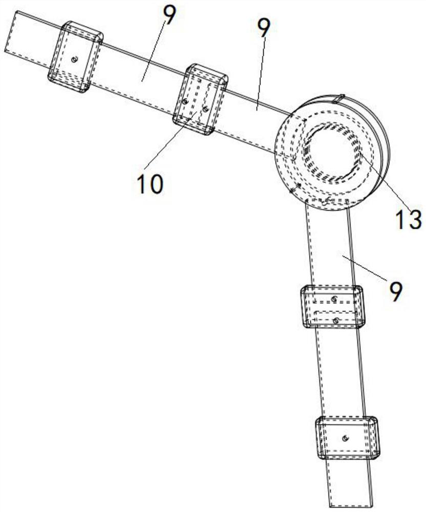
[0045] The straightening device includes eight locking blocks 1, one side of the locking block 1 includes more than one screw hole 2, the middle of the locking block 1 includes a hole, and the connecting plate 9 can be inserted into the hole in the middle of the locking block 1 and then be inserted into the middle of the locking block 1. Screw hole 2 and the screw inserted into screw hole 2 are pressed;

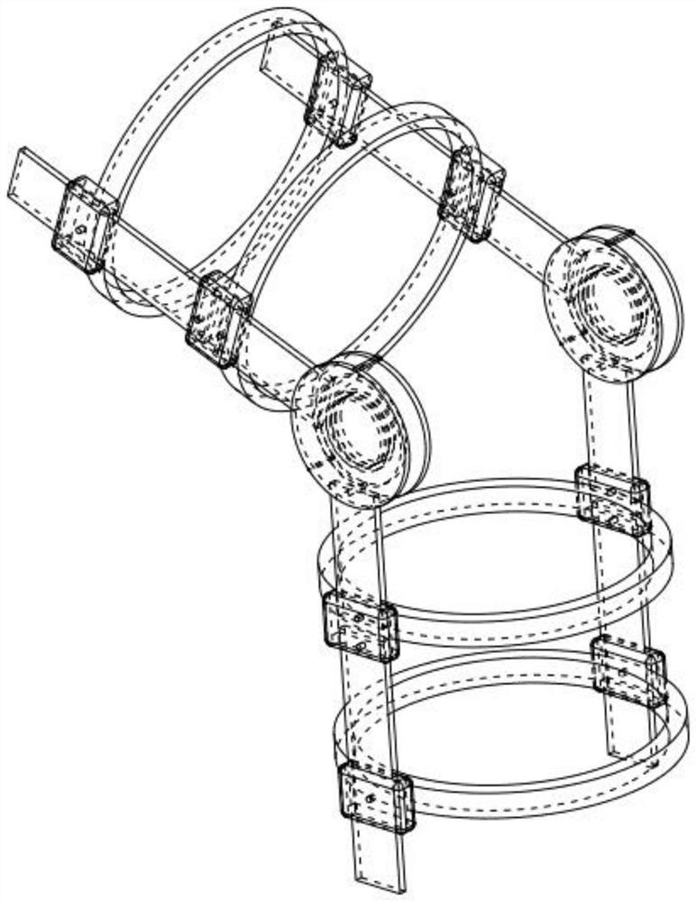
[0046] The locking block 1 includes a groove 14, the shape of the groove 14 is a convex-shaped structure, and the two sides of the elastic skin-fitting structure 3 are correspondingly arranged with raised blocks 15, and the raised blocks 15 can fit into the groove 14; The presentation of this paragraph can refer to the last two figures.

[0047] The correction device is divided into a thigh wrap...

Embodiment 2

[0055] Embodiment 2: As a further improved solution or a parallel solution or an optional independent solution, the elastic skin-sticking structure 3 is an elastic band. The substantial technical effects and the realization process of the technical solutions here, that is, the basic functions are as follows:

[0056] The elastic band is the preferred structure of this patent, and similar realization structures are all within the protection scope of this patent.

Embodiment 3

[0057] Embodiment 3: As a further improved solution or a parallel solution or an optional independent solution, the outer surface 4 of the elastic skin-fitting structure 3 includes a layer of felt layer. The substantial technical effects and the realization process of the technical solutions here, that is, the basic functions are as follows:

[0058] This embodiment is mainly implemented with the following scheme: when the knee pad cloth 11 is an open cloth, the felt layer contained on the cloth can be bonded to a layer of felt layer contained on the outer surface 4 . This method can also be used to protect the knee when it is actually used as a corrective structure.


PUM


Abstract

The invention relates to the field of medical care, in particular to a bone joint correction device capable of increasing or decreasing structures to become kneecaps. The correcting device comprises eight clamping blocks (1) and is divided into a thigh covering space (5) and a shank covering space (6) by taking two groups of hinge joints (7) as boundaries; the two groups of hinge joints (7) are of a structure in which the two clamping blocks (1) are hinged to each other and can rotate; the thigh covering space (5) comprises two groups of loose and tight skin-attaching structures (3); the shank coating space (6) comprises two groups of loose and close skin structures (3); the clamping block (1), the connecting plate (9), the hinge joint (7) and the loose and close skin structure (3) can be disassembled into independent individuals.

Description

technical field [0001] The invention relates to the field of medical care, in particular to a bone joint correction device whose structure can be increased or decreased to become a knee brace. Background technique [0002] The existing knee joint correction has a complex structure and is not easy to assemble. It is very troublesome and bulky for people to wear, and it will cause a lot of wear and tear to human skin. Basically, a lot of people suffer from knee correction. [0003] In the prior art, the knee brace is a knee brace, and the corrective structure is a corrective structure, and there is no mutually interchangeable structure. [0004] In the actual medical process, knee joint correction is only required for a period of time. After the knee joint correction is completed, this part of the corrective structure is basically lost. [0005] There is an urgent need for an orthopedic device that can be used for multiple purposes and is easy to disassemble. [0006] Searc...

Claims


Application Information

Patent Timeline
IPC IPC(8): A61F5/01A61F7/00A41D13/06
CPCA61F5/0109A61F7/007A41D13/065A61F2007/0042
Inventor 刘艳武王玲娟赵诣林赵轶男陈晓超李志全吴尧平
Owner AIR FORCE MEDICAL UNIV
Why Eureka
Try Eureka