Automatic extrusion multi-chamber liquid storage bag device
An automatic extrusion and liquid storage bag technology, applied in the field of medical equipment, can solve the problems of inconvenient operation, low efficiency of liquid medicine, and time-consuming, etc., and achieve the effect of saving time and effort, and simple and convenient operation
- Summary
- Abstract
- Description
- Claims
- Application Information
AI Technical Summary
Problems solved by technology
Method used
Image

Examples
Embodiment 1
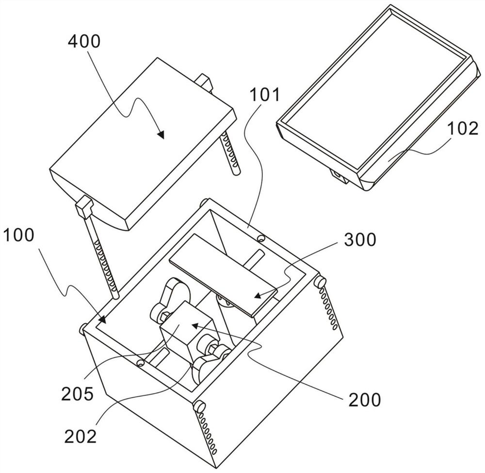
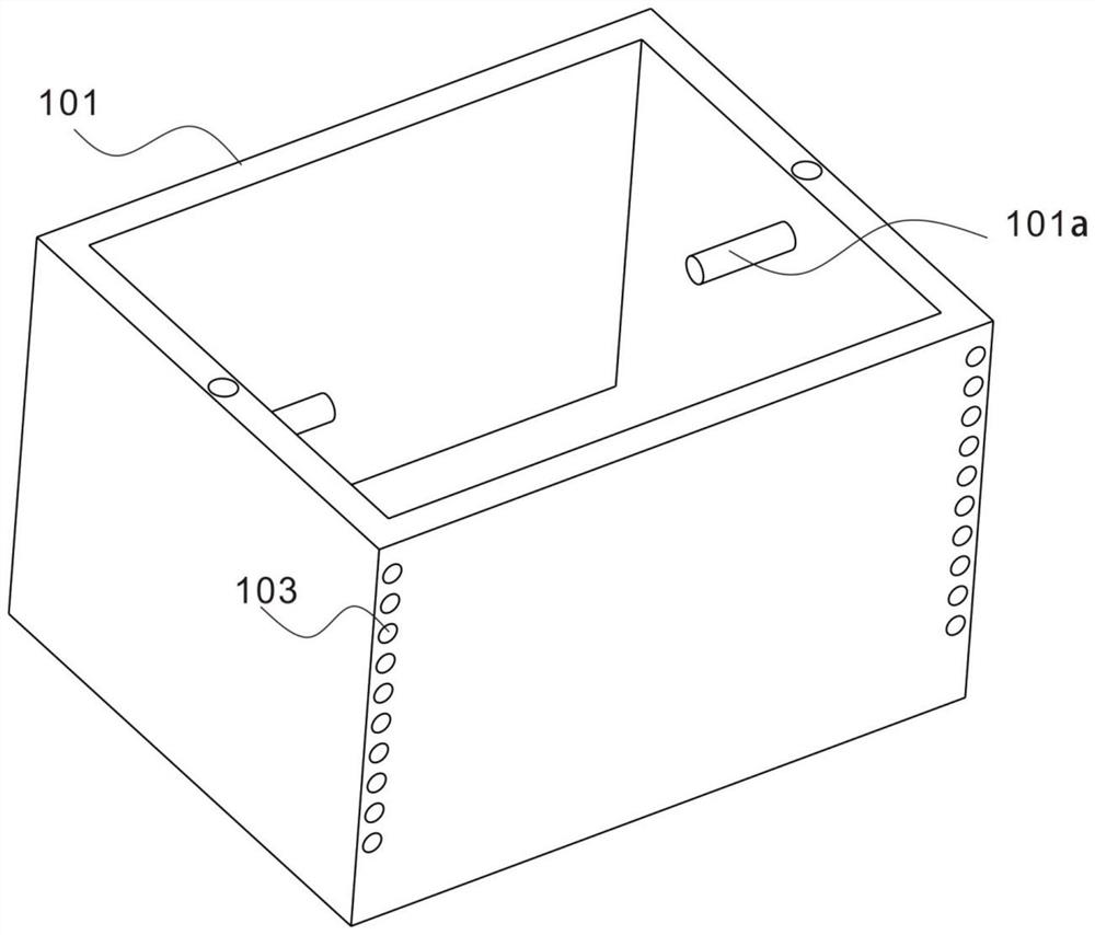
[0041] refer to Figures 1 to 9 , this embodiment provides an automatic extrusion multi-chamber liquid storage bag device, including a housing assembly 100, including a housing 101 and a tray 102, and the tray 102 is hinged with the housing 101;
[0042] The drive assembly 200 includes a drive shaft 201, a support rod 202, a first drive disk 203, a second drive disk 204 and a drive motor 205. The drive shaft 201 is connected to the support rod 202, the support rod 202 is connected to the housing 101, and the first drive The disk 203 is connected with one end of the drive shaft 201, and the second drive disk 204 is connected with the other end of the drive shaft 201;
[0043] The self-adjusting assembly 300 includes an adjustment piece 301 and a support base 302, the adjustment piece 201 is connected with the support base 302, and the support base 302 is connected with the housing 101;
[0044] The extrusion assembly 400 includes a extrusion plate 401 and an insertion rod 402 ...
Embodiment 2
[0052] refer to Figures 1 to 9 The difference between this embodiment and the previous embodiment is that the edge of the tray 102 is provided with a chamfer 102c, and the setting of the chamfer 102c prevents the edge of the tray 102 from colliding with the casing 101 during the shaking process.
[0053] The end of the drive shaft 201 is provided with a fixed block 201a, and the fixed block 201a has a rectangular parallelepiped structure;
[0054] The first drive plate 203 is provided with a first fixing hole 203a, the second drive plate 204 is provided with a second fixing hole 204a, the first fixing hole 203a is connected to one end of the fixing block 201a, and the second fixing hole 204a is connected to the other end of the fixing block 201a connection;
[0055] The cuboid structure of the fixing block 201a ensures the assembly stability of the fixing block 201a and the first fixing hole 203a, and the fixing block 201a and the second fixing hole 204a. The fixing block 20...
Embodiment 3
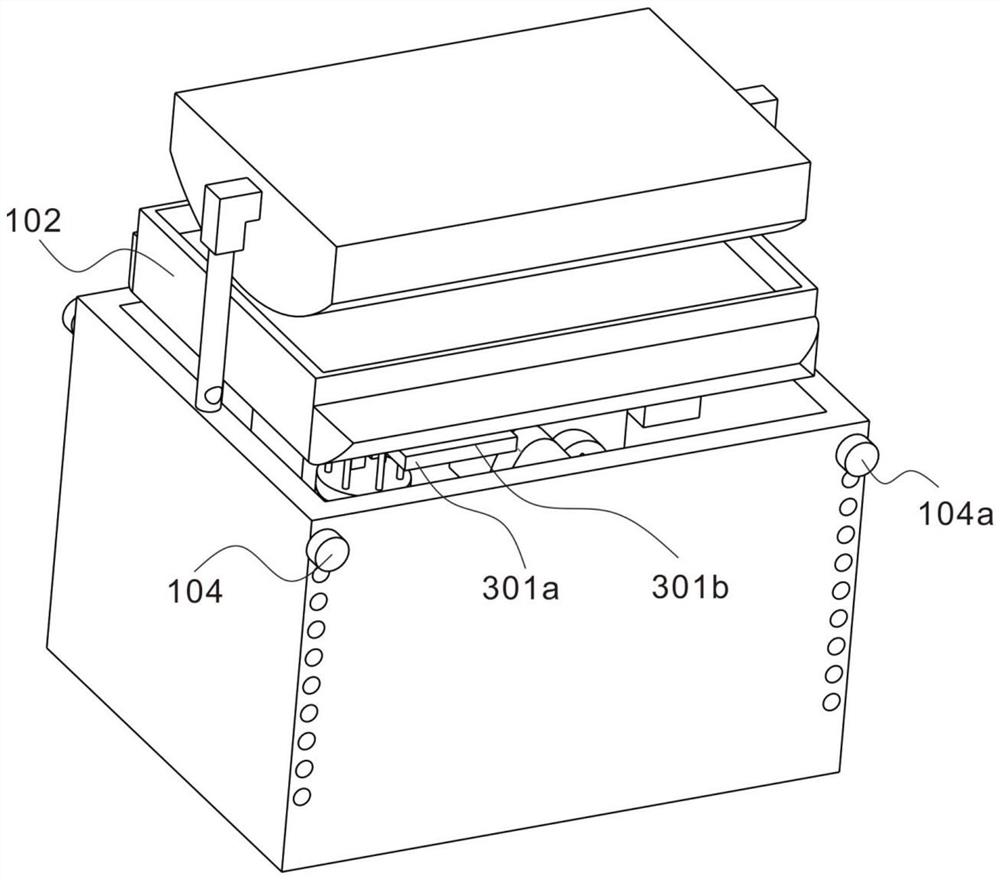
[0062] refer to Figures 1 to 9 The difference between this embodiment and the previous embodiment is that the adjustment member 301 is provided with an adjustment disk 301a, an adjustment gap 301b is formed between the adjustment disk 301a and the tray 102, and the adjustment gap 301b also changes when the tray 102 shakes. , because the first drive plate 203 and the second drive plate 204 push up the tray 102 alternately when rotating, so that the size of the adjustment gap 301b also changes periodically. When the adjustment plate 301a and the tray 102 shake normally, the adjustment gap 301b It does not affect the normal shaking of the device, only when one side of the tray 102 is too low, the adjustment gap 301b at a certain point is zero, and the adjustment member 301 provides a certain support force for the too low side of the tray 102, so that the tray 102 shakes more smoothly When the parts in the device are worn out or other unexpected conditions cause the tray 102 to s...
PUM
 Abstract
Description
Claims
Application Information
 - R&D Engineer
- R&D Manager
- IP Professional
- Industry Leading Data Capabilities
- Powerful AI technology
- Patent DNA Extraction
Browse by: Latest US Patents, China's latest patents, Technical Efficacy Thesaurus, Application Domain, Technology Topic.
© 2024 PatSnap. All rights reserved.Legal|Privacy policy|Modern Slavery Act Transparency Statement|Sitemap