Punching equipment for processing shuttle peg sleeve

A technology of punching equipment and bobbins, which is applied in the field of bobbin case processing, can solve problems such as bobbin case shaking, lower quality of bobbin case finished products, and impact on punching accuracy of punching equipment, so as to improve buffering effect and punching speed. Effect of Hole Precision

Pending Publication Date: 2022-07-15
宁波鸿云精密机械有限公司
View PDF0 Cites 0 Cited by
  • Summary
  • Abstract
  • Description
  • Claims
  • Application Information

AI Technical Summary

Problems solved by technology

[0004] In order to make up for the deficiencies of the prior art and solve the problem that the existing bobbin case is prone to shaking when the end of the bobbin case is arc-shaped during the punching process of the punching equipment , which in turn causes the punching accuracy of the punching equipment to be affected, reducing the quality of the finished product of the bobbin case. The present invention proposes a punching device for bobbin case processing

Method used


Image

  • Punching equipment for processing shuttle peg sleeve
  • Punching equipment for processing shuttle peg sleeve
  • Punching equipment for processing shuttle peg sleeve

Examples


Embodiment 1

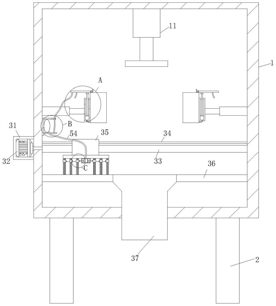
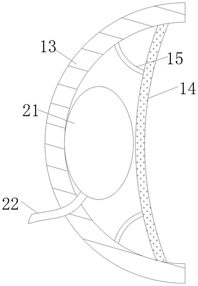
[0027] see Figure 1-7 As shown, a punching device for bobbin sleeve processing includes a processing box 1; the inner wall of the processing box 1 is fixed with a punching device 11; the inner wall of the processing box 1 is fixed with an electric pusher The rod 12 is located at the bottom of the punching equipment 11; the side end of the electric push rod 12 is fixed with a splint 13; the inner side wall of the splint 13 is fixed with a buffer pad 14; the side end of the buffer pad 14 is fixed The elastic piece 15 is connected, and the other end of the elastic piece 15 is fixed on the inner side wall of the splint 13; during operation, when the existing bobbin sleeve is punched, the end of the bobbin sleeve is arc-shaped, resulting in punching. During the punching process of the equipment 11, the bobbin case is prone to shaking, which in turn affects the punching accuracy of the punching equipment 11 and reduces the finished product quality of the bobbin case. By placing the...

Embodiment 2

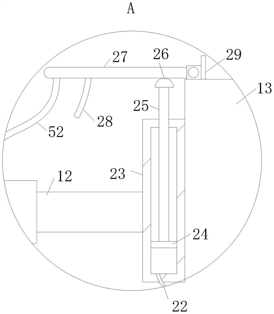
[0035] see Figure 8 As shown in Comparative Example 1, as another embodiment of the present invention, the end of the guide plate 28 is fixed with a protective pad 6; during operation, when the push block 26 presses the guide plate 28 for a long time, it will When the problem of wear and tear occurs, the protective pad 6 is installed to improve the protective effect between the guide plate 28 and the push block 26, so as to avoid the problem of fracture caused by wear and tear.

[0036] Working principle, when the existing bobbin sleeve is punching, the end of the bobbin sleeve is arc-shaped, which causes the bobbin sleeve to shake easily during the punching process of the punching equipment 11, which in turn leads to punching. The punching accuracy of the equipment 11 is affected, and the quality of the finished product of the bobbin case is reduced. By placing the bobbin case on the side end of the splint 13, and then opening the electric push rod 12, the splint 13 is moved...


PUM


Abstract

The invention belongs to the technical field of cop latch sleeve machining, and particularly relates to punching equipment for cop latch sleeve machining. The side end of an electric push rod is fixedly connected with a clamping plate; the inner side walls of the clamping plates are fixedly connected with buffering pads. The side end of the buffer pad is fixedly connected with an elastic piece, and the other end of the elastic piece is fixedly connected to the inner side wall of the clamping plate. The shuttle peg sleeve is placed at the side end of the clamping plate, then the electric push rod is opened, the clamping plate is driven to move towards the middle part, the shuttle peg sleeve is clamped and fixed, when the clamping plate extrudes the end part of the shuttle peg sleeve, the end part of the shuttle peg sleeve extrudes the buffer cushion, so that the buffer cushion is stressed to be bent, and a protection effect is achieved; the elastic piece is extruded to generate elastic force for buffering, so that the buffering effect on the shuttle peg sleeve is improved, and the problem that the quality of finished products is affected due to shaking of the shuttle peg sleeve in the machining process is solved.

Description

technical field [0001] The invention relates to the technical field of bobbin case processing, in particular to a punching device used for bobbin case processing. Background technique [0002] During the working process of the sewing machine, the phenomenon of running out of needles is almost likely to occur. This is because the amount of bobbin thread drawn out by the suture thread of the bobbin case under the action of the tension adjustment spring is small, and the sewing machine starts to sew or automatically breaks the thread and then sew again. When making, the upper thread cannot be firmly grasped with the bottom thread, and the needle will run short. [0003] In the current prior art, when the existing bobbin sleeve is punched, the end of the bobbin sleeve is in the shape of an arc, resulting in the problem that the bobbin sleeve is prone to shaking during the punching process of the punching equipment, which leads to The punching accuracy of the punching equipment ...

Claims


Application Information

Patent Timeline
Patent Type & Authority Applications(China)
IPC IPC(8): B21D28/34B21D43/00B08B1/00
CPCB21D28/34B21D43/003B08B1/002B08B1/008
Inventor 王乾云
Owner 宁波鸿云精密机械有限公司
Why Eureka
Try Eureka