
Automatic welding method and device for end of round drill rod

An automatic welding and drill pipe technology, applied in welding equipment, non-electric welding equipment, metal processing equipment, etc., can solve the problems of untraceable welding quality, harsh manual operating environment, loss of parameter records, etc., to achieve stable and reliable production quality, artificial Small influence of factors and consistent effect

Pending Publication Date: 2022-07-15
BEIJING RES INST OF AUTOMATION FOR MACHINERY IND
View PDF0 Cites 2 Cited by
  • Summary
  • Abstract
  • Description
  • Claims
  • Application Information

AI Technical Summary

Problems solved by technology

[0010] 1) During the production process, the loading and unloading of male, female, and pipe bodies is done manually or manually transported to the friction welding table, and the friction welding machine comes with a truss gripper to realize loading, which is labor-intensive ;
[0011] 2) The loading and unloading of heavy drill pipes (20-70kg) requires two people to carry or hoist with truss trucks, which is inefficient;
[0012] 3) The manual operation environment is harsh;
[0013] 4) The parameter records of joint welding process are lost, and the welding quality cannot be traced;
[0014] 5) Manual participation in the whole process of production, high failure rate

Method used


Image

  • Automatic welding method and device for end of round drill rod
  • Automatic welding method and device for end of round drill rod
  • Automatic welding method and device for end of round drill rod

Examples


Embodiment Construction

[0091] Below in conjunction with accompanying drawing, structure principle and working principle of the present invention are described in detail:

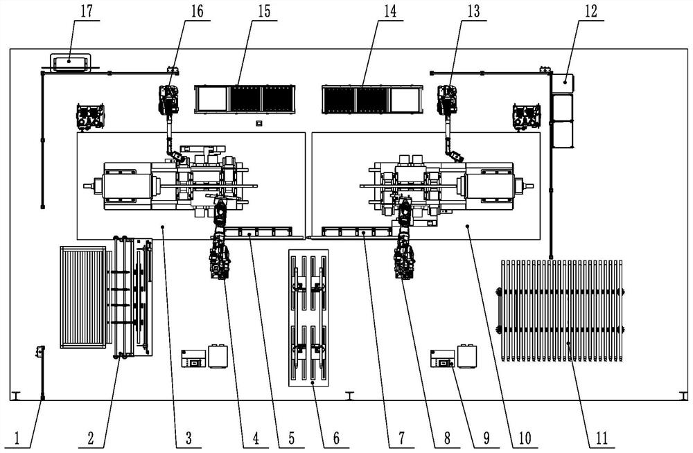
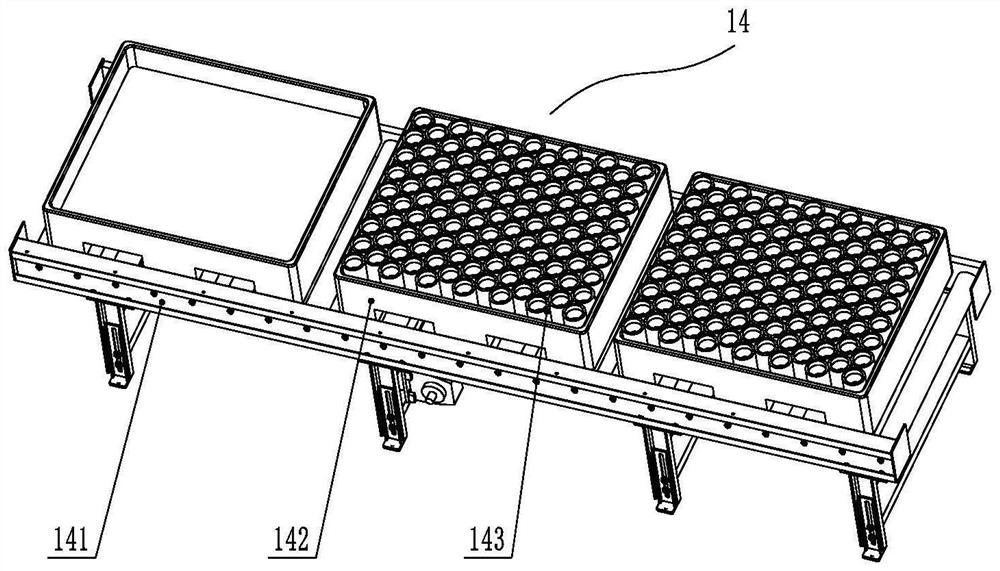
[0092] see figure 2 , figure 2 It is a schematic structural diagram of an apparatus according to an embodiment of the present invention. The automatic welding device for round drill pipe ends of the present invention includes: a male friction welding machine 3; The head friction welding machine 10 is a continuous friction welding machine; the pipe body transfer robot 4 is arranged on one side of the male head friction welding machine 3, and a pipe body buffer material rack 5 is correspondingly provided on one side of the pipe body transfer robot 4; The male head transfer robot 16 is arranged on the other side of the male head friction welding machine 3, one side of the male head transfer robot 16 is provided with a male head feeding line 15, and a male head feeding line 15 is provided with a The code recognition camera 154 is...


PUM


Abstract

The invention discloses an automatic welding method and device for the end of a round drill rod, and the method comprises the steps that a male head joint transfer robot recognizes and grabs a male head, reads a material code of the male head, and places the male head into a clamp of a male head friction welding machine to be clamped; the pipe body transfer robot grabs the pipe body and places the pipe body on a male head friction welding machine, a male head and one end of the pipe body are welded together, the concentricity of the pipe body and the male head is detected after welding is completed, and a semi-finished drill rod which is detected to be qualified is obtained; the female head transfer robot recognizes and grabs one female head, and the female head is placed in a clamp of the female head friction welding machine and clamped; and the drill rod transfer robot grabs the semi-finished drill rod and places the semi-finished drill rod on the female head friction welding machine, the female head and the other end of the pipe body of the semi-finished drill rod are welded together, the concentricity of the pipe body and the female head is detected after welding is completed, and the finished drill rod which is detected to be qualified is obtained. The invention further provides an automatic welding device for the ends of the round drill rods. Production efficiency can be improved, labor intensity is reduced, and personal safety is guaranteed.

Description

technical field [0001] The invention relates to automatic friction welding technology, in particular to an automatic welding method and device for circular drill pipe ends used for automatic welding of both ends of a circular drill pipe and a rod body. Background technique [0002] The drill pipe is an important part of the drilling rig, and is often used in the drilling construction of underground gas extraction, water exploration and drainage in coal mines. During the drilling process, the drill pipe is in a complex working state and is often subjected to tension, compression, bending, shearing and torsion. , hydraulic, vibration and other alternating loads, and accompanied by the scouring of the liquid, so the drill pipe often breaks during drilling, which affects normal production and causes loss of human and financial resources, which has a great impact on coal mine safety. [0003] In the production process of drill pipe, end welding is an important production process,...

Claims


Application Information

Patent Timeline
Patent Type & Authority Applications(China)
IPC IPC(8): B23K20/12B23K20/26
CPCB23K20/12B23K20/1255B23K20/126B23K20/26
Inventor 郭聪聪刘华中刘俊华娄亚军
Owner BEIJING RES INST OF AUTOMATION FOR MACHINERY IND
Learn More