
Spindle impeller head for drum-type shot blasting machine and shot blasting equipment

A shot blasting machine and drum type technology, which is used in metal processing equipment, used abrasive processing devices, abrasive jet machine tools, etc. problem, to achieve the effect of controllability, shot blasting time and work efficiency improvement

Pending Publication Date: 2022-07-15
SHANDONG UNIV +1
View PDF9 Cites 0 Cited by
  • Summary
  • Abstract
  • Description
  • Claims
  • Application Information

AI Technical Summary

Problems solved by technology

[0005] However, the inventors found that the current traditional drum type shot blasting machine needs to install multiple blasting devices at different positions on both sides of the drum to cover the processing range inside the drum through axial blasting, resulting in an excessive number of blasting devices And the processing angle is limited. At the same time, the structure of the traditional hopper for conveying shot blasting is simple, and it is impossible to control the shot blasting amount and shot blasting time.

Method used


Image

  • Spindle impeller head for drum-type shot blasting machine and shot blasting equipment
  • Spindle impeller head for drum-type shot blasting machine and shot blasting equipment
  • Spindle impeller head for drum-type shot blasting machine and shot blasting equipment

Examples


Embodiment Construction

[0029] It should be noted that the following detailed description is exemplary and intended to provide further explanation of the invention. Unless otherwise defined, all technical and scientific terms used herein have the same meaning as commonly understood by one of ordinary skill in the art to which this invention belongs.

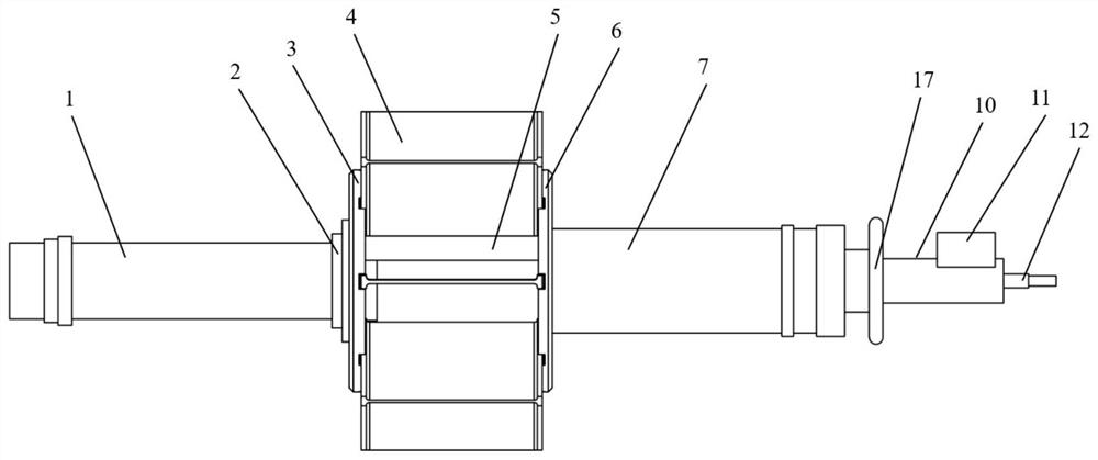
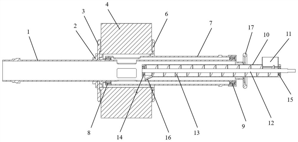
[0030] like figure 1 , figure 2 as well as Figure 5 As shown, the main shaft shot blasting device installed in the drum type shot blasting machine provided by the embodiment of the present invention includes a main shaft part, and the main shaft part mainly includes two parts: a shot blasting structure and a feeding structure. The shot structure mainly includes a shot dividing pipe 1, a directional pipe 7 and a shot blasting rotor, etc. The feeding mechanism includes a feeding pipe 10 and a screw feeding shaft 12 arranged inside the feeding pipe, etc., wherein the shot blasting structure is installed on the existing drum. The two end faces of the d...


PUM


Abstract

The invention relates to a main shaft impeller head for a drum-type shot blasting machine and shot blasting equipment. Belongs to the technical field of impeller heads. The main shaft impeller head comprises a main shaft component, the main shaft component is arranged in a roller of a shot blasting machine, the main shaft component comprises a shot distributing pipe, a directional pipe and a shot blasting rotor which are coaxially arranged, one end of the shot distributing pipe is rotationally connected with the first end face of the roller of the shot blasting machine, and the other end of the shot distributing pipe is embedded in the first end of the directional pipe; the shot distributing pipe can rotate around the axis of the shot distributing pipe, the second end of the directional pipe is rotationally arranged on the second end face of the shot blasting machine roller, a plurality of first openings are formed in the outer wall face of the part, nested in the directional pipe, of the shot distributing pipe in the circumferential direction, a second opening is formed in the outer wall face of the directional pipe, and the shot blasting rotor is installed on the shot distributing pipe. And the shot blasting rotor comprises shot blasting blades, and when the shot distributing pipe rotates, shot blasting in the shot distributing pipe can sequentially pass through the first opening and the second opening and collides with the shot blasting blades to be thrown into a roller of the shot blasting machine.

Description

technical field [0001] The invention belongs to the technical field of shot blasting machines, and in particular relates to a main shaft shot blasting machine and shot blasting equipment for a drum type shot blasting machine. Background technique [0002] The statements herein merely provide background related to the present invention and do not necessarily constitute prior art. [0003] The drum shot blasting machine is usually used in the field of foundry machinery. Its working purpose is to carry out surface treatment such as cleaning residual sand, removing oxide layer, surface strengthening, etc. on the workpiece generated by casting or forging. The dead corners of the cavity are cleaned to make the attachments on the inner wall of the workpiece fall off, improve the smoothness and effectively strengthen the surface and increase the life of the parts. Since the workpiece is continuously turned over with the rolling of the drum during the shot blasting process, it is re...

Claims


Application Information

Patent Timeline
IPC IPC(8): B24C3/30B24C7/00B24C9/00
CPCB24C3/30B24C7/0092B24C9/00
Inventor 刘继凯周龙李磊邹斌冀浩楠
Owner SHANDONG UNIV
Learn More