
Impeller structure of washing machine

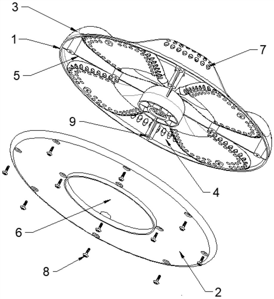
A washing machine and pulsator technology, applied in the field of washing machines, can solve problems such as affecting the safety of clothing and human health, increase labor, and be difficult to clean, so as to ensure the safety of clothing and human health, reduce the probability of clothing damage, and improve the experience. Effect

Pending Publication Date: 2022-07-15
赵红波
View PDF0 Cites 0 Cited by
  • Summary
  • Abstract
  • Description
  • Claims
  • Application Information

AI Technical Summary

Problems solved by technology

Among them, the residual dandruff and dirt after use of the existing pulsator washing machine needs to be promptly removed from the filter box for manual cleaning, which increases the labor load and reduces the consumer's experience. If it is not cleaned in time or forgotten to clean, the dirt will In the humid and shaded environment in the washing machine, it is easy to breed bacteria, even rot and smell, which affects the safety of clothes and human health; moreover, the bottom of the pulsator of the pulsator washing machine and between the washing tub and the shell are also places where dirt is easy to remain. However, these parts are difficult to clean, and it is usually necessary to hire professional maintenance personnel to come to the door for thorough dismantling and cleaning, and a certain service fee needs to be paid for each cleaning; in addition, the washing principle of the pulsator washing machine mainly relies on the friction between clothes and The friction between the clothes and the inner wall of the washing tub and the pulsator is used to achieve the purpose of washing the clothes, which leads to a common problem in the pulsator washing machine, that is, although the cleanliness of the laundry is high, the wear and damage to the clothes are also greater.

Method used


Image

  • Impeller structure of washing machine
  • Impeller structure of washing machine
  • Impeller structure of washing machine

Examples


Embodiment 1

[0023] like figure 1 and Figure 5 As shown, a washing machine pulsator structure includes a disc-shaped pulsator panel 1, and four stirring ridges 3 are fixed radially on the front of the pulsator panel. An upright water guide vane 5 is fixed in the center along its length direction in the groove 4, the back side of the pulsator panel is buckled with the pulsator back plate 2, and the pulsator back plate and the pulsator panel are arranged between the pulsator back plate and the pulsator panel. A water guide cavity is formed by interlocking with each other. The center of the pulsator back plate is provided with a water inlet 6, and the front of the pulsator panel is provided with a number of water outlet holes 7. The water inlet and each of the water outlet holes are the same as the The water guide cavity is connected.

[0024] The pulsator back plate is fixedly connected to the pulsator panel through a plurality of mounting screws 8, and the back of the pulsator panel is f...

Embodiment 2

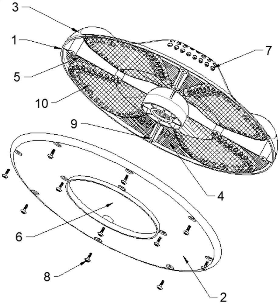
[0028] like figure 2 and Figure 5 As shown, a washing machine pulsator structure includes a disc-shaped pulsator panel 1, and four stirring ridges 3 are fixed radially on the front of the pulsator panel. An upright water guide vane 5 is fixed in the groove 4 along its length direction, the back side of the pulsator panel is buckled with the pulsator back panel 2, and the pulsator back panel and the pulsator panel are mutually connected. Buckle to form a water guide cavity, the center of the pulsator back plate is provided with a water inlet 6, and the front of the pulsator panel is provided with a number of water outlet holes 7, the water inlet and each of the water outlet holes are connected with the water guide The water chamber is connected.

[0029] The inner side of each water outlet is provided with a filter screen 10, and the filter screen is a layer of filter screen laid integrally on the uneven back surface of the pulsator panel (ie, the water inlet side of each w...

Embodiment 3

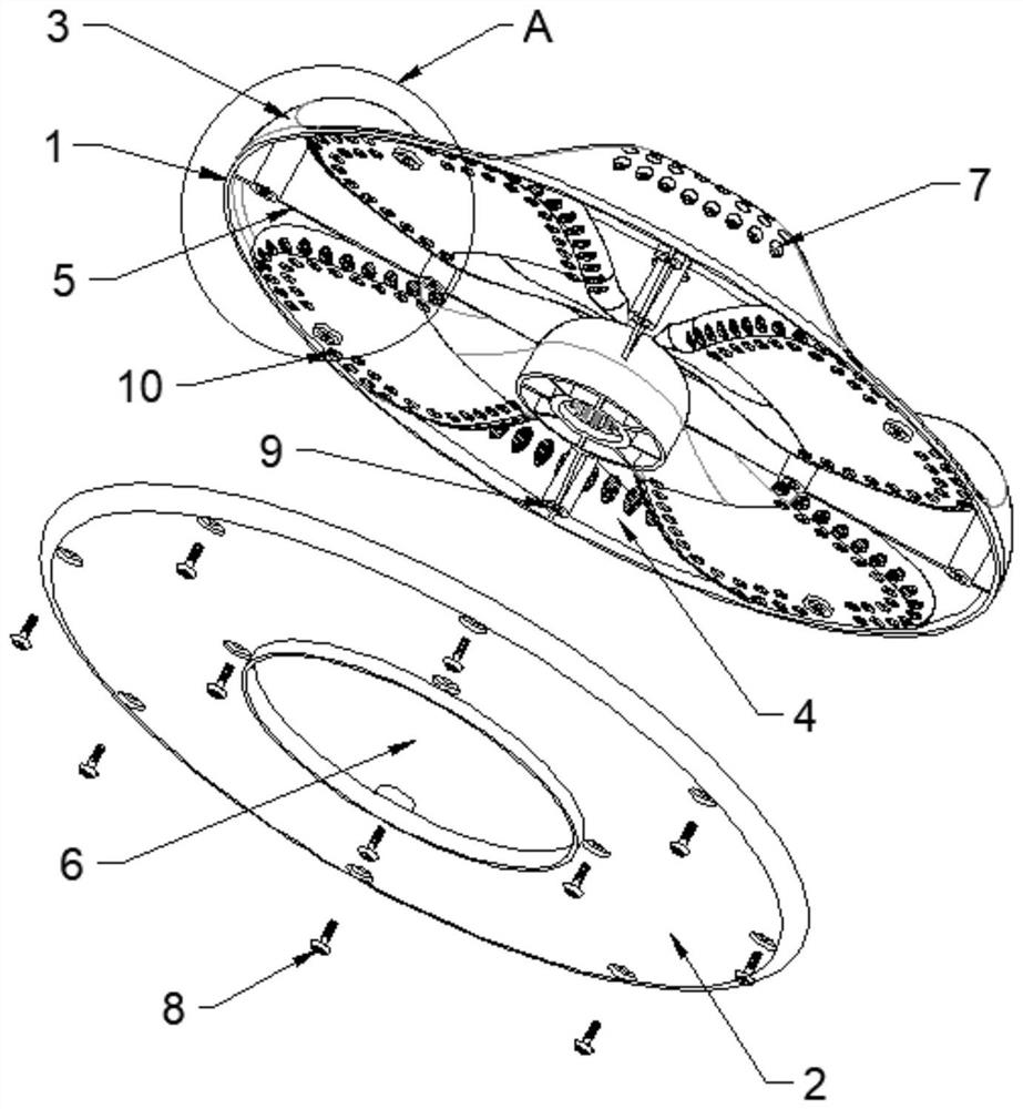
[0034] like Figure 3-5 As shown, a washing machine pulsator structure includes a disc-shaped pulsator panel 1, and four stirring ridges 3 are fixed radially on the front of the pulsator panel. An upright water guide vane 5 is centrally fixed in the groove 4 along its length direction. The back side of the pulsator panel is buckled and provided with a disc-shaped pulsator back plate 2. The pulsator back plate is connected to the pulsator. The panels are buckled with each other to form a water guide cavity, the center of the pulsator back plate is provided with a water inlet 6, and the front of the pulsator panel is provided with a number of water outlet holes 7, the water inlet and each of the water outlet holes are communicated with the water guide cavity.

[0035] A filter screen 10 is arranged inside each of the water outlet holes, and the filter screen is a small filter screen separately arranged in each of the water outlet holes, and each filter screen is integrally cast...


PUM


Abstract

The invention belongs to the technical field of washing machines, and particularly relates to a washing machine impeller structure which comprises a disc-shaped impeller panel, a plurality of stirring ribs are fixedly arranged on the impeller panel in a radial mode, a plurality of vertical water guide blades are arranged on the back face of the impeller panel in a radial mode, and an impeller back plate is arranged on the back side of the impeller panel in a buckled mode. The impeller back plate and the impeller panel are mutually buckled to form a water guide cavity, a water inlet is formed in the impeller back plate, a plurality of water outlet holes are formed in the front face of the impeller panel, the water inlet and the water outlet holes are communicated with the water guide cavity, and a filter screen is arranged on the inner side of each water outlet hole. Washing water is turned and circulated from bottom to top through the impeller structure design, and clothes abrasion is reduced; when the washing machine drains water, the filter screen is reversely self-cleaned and washed, so that the trouble of manual cleaning is avoided, residual dirt is prevented from breeding bacteria, and clothes safety and human health are guaranteed.

Description

technical field [0001] The invention belongs to the technical field of washing machines, and in particular relates to a washing machine pulsator structure. Background technique [0002] With the improvement of people's living standards and the advancement of home appliance research and technology, automatic washing machines have entered thousands of households. There are mainly two types of automatic washing machines on the market: front-loading washing machines and pulsator washing machines. Among them, the residual dander and dirt in the existing pulsator washing machine need to be deducted in time for manual cleaning, which increases the labor and reduces the consumer's favorable experience. In the damp and shaded environment of the washing machine, it is easy to breed bacteria, even rot and smell, which affects the safety of clothes and human health; and the bottom of the pulsator of the pulsator washing machine and between the washing tub and the shell are also easy to ...

Claims


Application Information

Patent Timeline
Patent Type & Authority Applications(China)
IPC IPC(8): D06F17/10D06F39/10
CPCD06F17/10D06F39/10
Inventor 赵红波赵梓辰
Owner 赵红波
Learn More