
Experimental system for representing interlayer interference degree of reservoir

An interlayer interference, experimental system technology, applied in permeability/surface area analysis, suspension and porous material analysis, measurement devices, etc. Achieve the effect of ensuring accuracy and uniform force

Pending Publication Date: 2022-07-15
SOUTHWEST PETROLEUM UNIV
View PDF0 Cites 0 Cited by
  • Summary
  • Abstract
  • Description
  • Claims
  • Application Information

AI Technical Summary

Problems solved by technology

[0004] First, on the device, there is only one experimental core for simulating a single-layer reservoir, which cannot effectively simulate the lateral interference of the porosity and permeability of each oil layer in the actual reservoir;
[0005] Second, the cores for simulating multiple reservoirs are not connected to each other vertically, that is, only the reservoirs with less severe channeling in the vertical direction are simulated, but the reservoirs with interlayer interference cannot be effectively simulated;
[0006] Third, the current test method for the degree of interlayer interference has limitations and cannot fully cope with various types of reservoirs;
[0007] Fourth, when the confining pressure is applied to the core sample, when the pressure generated by the pressurized fluid acts on the outer wall of the core sample, it is easy to cause uneven stress on the core sample, which in turn leads to the infiltration test of the core sample. Errors occur, which is not conducive to obtaining accurate parameter data in simulation experiments

Method used


Image

  • Experimental system for representing interlayer interference degree of reservoir
  • Experimental system for representing interlayer interference degree of reservoir
  • Experimental system for representing interlayer interference degree of reservoir

Examples


Embodiment 1

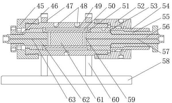
[0035] like Figure 1 to Figure 5 As shown, this embodiment includes a constant pressure and constant speed pump 1, a first six-way valve 2, a simulated formation water storage tank 5, a simulated formation oil storage tank 6 and a second six-way valve 9, and also includes a ring pressure pump 44, a parallel connection The first six-way valve 2 is connected with the simulated formation water storage tank 5 and the simulated formation oil storage tank 6 respectively, and receives the pressure of the constant pressure and constant speed pump 1 and provides simulated formation pressure; The input ends of the two-six-way valve 9 are respectively connected to the simulated formation water storage tank 5 and the simulated formation oil storage tank 6, and the output ends of the second six-way valve 9 are respectively connected to multiple sets of grippers in one-to-one correspondence; The device includes two clamping pipe bodies connected in series, and an air outlet is provided on ...

Embodiment 2

[0044] like figure 2 and Figure 4 As shown, on the basis of Embodiment 1, this embodiment defines a blocking mechanism for closing both ends of the holder, including a left plug 62 and a right plug 56. In the middle of the left plug 62, the right plug The middle part of the head 56 is respectively provided with a liquid inlet hole 63 and a liquid outlet hole 57 which are communicated with the inside of the clamping pipe body; among the two clamping pipe bodies belonging to the same group, the liquid inlet hole 63 of one clamping pipe body is connected to the second and sixth clamping pipe bodies. The output end of the through valve 9 is connected, the liquid outlet hole 57 of the clamping pipe body is communicated with the liquid inlet hole 63 of the other clamping pipe body, and the liquid outlet hole 57 of the other clamping pipe body is provided with a back pressure valve ; On the outer wall of the outer end of the left plug 62, there is a matching shaft sleeve 46, the s...

Embodiment 3

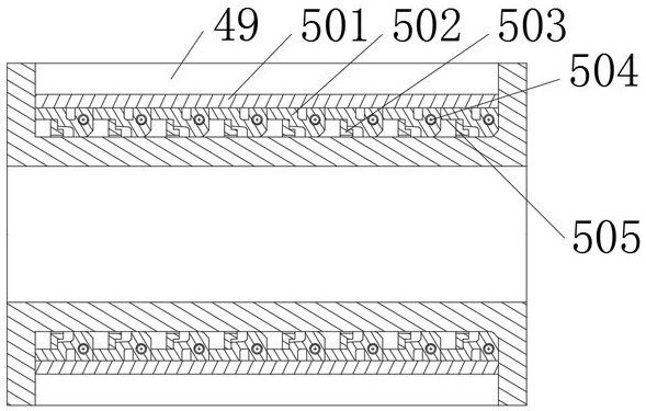
[0050] like figure 2 and image 3 As shown, on the basis of Embodiment 1 and Embodiment 2, this embodiment serves as a fine-tuning mechanism 50 for improving the accuracy of simulated experimental data, including a plurality of arc-shaped plates 501 uniformly arranged along the circumference of the rubber cylinder 51, and The inner walls of the plurality of arc-shaped plates 501 are connected by an adjustment ring, and both end faces of the arc-shaped plates 501 are in contact with the flange side walls. The adjustment ring includes a plurality of rubber sealing rings 502 whose end faces are connected to each other. The part of the ring is in contact with the outer wall of the rubber cylinder 51, and a limit ring 503 is provided on the non-contact parts of the plurality of sealing rings 502. The limit ring 503 is sleeved on the outer circumferential wall of the rubber cylinder 51, and the inner wall of the limit ring 503 A gap 505 is left between the outer circumferential wa...


PUM


Abstract

The invention discloses an experimental system for representing the interlayer interference degree of reservoirs, which comprises a constant-pressure constant-speed pump, a first six-way valve, a simulated formation water storage tank, a simulated formation oil storage tank and a second six-way valve, and is characterized in that the first six-way valve is connected with the simulated formation water storage tank and the simulated formation oil storage tank respectively; the input end of the second six-way valve is connected with the simulated formation water storage tank and the simulated formation oil storage tank, and the output end of the second six-way valve is connected with the multiple sets of clamping devices in a one-to-one correspondence mode. Plugging mechanisms are arranged at the two ends of the clamping pipe body, and a fine adjustment mechanism is arranged on the outer circumferential wall of the rubber sleeve. According to the method, the rock core sample holders are optimally designed, confining pressure application is assisted, it is ensured that the outer wall of the rock core sample on each holder is stressed uniformly, and the transverse and longitudinal structures of the rock core holders are randomly combined according to the characteristics of a target reservoir to meet the layer series development guidance of any oil reservoir so as to ensure the accuracy of data obtained by a simulation experiment.

Description

technical field [0001] The invention relates to the technical field of core displacement experiments, in particular to an experimental system for characterizing the degree of interlayer interference in reservoirs. Background technique [0002] Layered extraction technology is an enhanced oil recovery measure widely used in oil and gas field development. The interlayer interference problem exists due to the serious vertical heterogeneity of the reservoir and the large coefficient of variation of the interlayer permeability. When oil wells with interlayer interference problems are produced in multi-layer commingled production, the high-permeability production layers will inhibit the development of low-permeability production layers to varying degrees, resulting in the production of multiple oil layers during commingled production is much smaller than the production of each layer when they are produced individually. sum. Therefore, the degree of interlayer interference is exp...

Claims


Application Information

Patent Timeline
IPC IPC(8): G01N15/08
CPCG01N15/0806G01N15/0826
Inventor 吕栋梁蔡黎军唐海张铠漓谢极严良龙杨健
Owner SOUTHWEST PETROLEUM UNIV
Features
  • Generate Ideas
  • Intellectual Property
  • Life Sciences
  • Materials
  • Tech Scout
  • Unparalleled Data Quality
  • Higher Quality Content
  • 60% Fewer Hallucinations
Learn More