Solar sunlight room

A sun room and solar energy technology, applied in the field of sun room, can solve the problems of inconvenient shading and heat insulation, inconvenient automatic cleaning, etc., and achieve the effect of saving electricity cost

Pending Publication Date: 2022-07-19
欣叶安康科技股份有限公司
View PDF0 Cites 1 Cited by
  • Summary
  • Abstract
  • Description
  • Claims
  • Application Information

AI Technical Summary

Problems solved by technology

[0005] The object of the present invention is to provide a kind of solar sun room, in order to solve the above background technology, the existing solar sun room is inconvenient to use the gravity of water to realize the automatic cleaning of the top, and at the same time it is inconvenient to use the gravity of water to realize the cleaning of the top. The problem of sunshade insulation

Method used


Image

  • Solar sunlight room
  • Solar sunlight room
  • Solar sunlight room

Examples


Embodiment 1

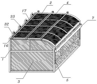
[0035] like Figure 1-5 , including an outer frame 1, a top frame 2 is fixed on the top of the outer frame 1, a common glass window 3 is installed on the side of the outer frame 1, and a solar glass 4 is fixed on the top of the top frame 2; The top position of the front end of the frame 1, and the inner side of the water storage frame 7 is fixed with a movable rod 6, and the movable rod 6 is vertically fitted and slidably installed in the movable groove 5 in a "T" shape, and the movable groove 5 is opened in the outer frame. On the outer side wall of 1, the side wall of the opening at the bottom of the water storage frame 7 is elastically slidably installed with a sealing plate 9 through the first spring 8, and the sealing plate 9 and the solid position at the bottom of the water storage frame 7 are provided with water outlet holes 10, And the solid part of the bottom of the water storage frame 7 is attached to the top of the sealing plate 9, and one end of the sealing plate 9...

Embodiment 2

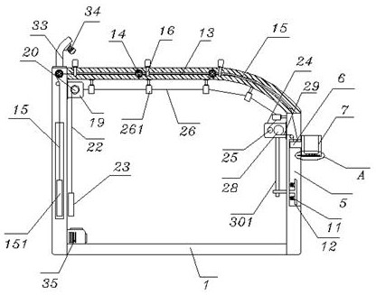
[0037] like figure 1 and Figure 6-10 , the placement box 19, the placement box 19 is fixed at the inner position of the top of the rear side of the outer frame 1, and the embedded bearing in the placement box 19 is installed with a mounting shaft 20, and the mounting shaft 20 is sleeved with a heat-insulating reflective roll 21, the mounting shaft The end of the 20 is wound with a second drawstring 22, and the bottom of the second drawstring 22 is fixed with a second weight bar 23, and the second weight bar 23 is located inside the rear side of the outer frame 1, and the front side of the outer frame 1. A transfer box 24 is fixed inside the top of the side, and a pull reel 25 is installed on one side of the embedded bearing of the transfer box 24, and a third pull rope 26 is wound around the end of the pull roll 25, and one end of the third pull rope 26 The limiting seat 261 is fixed to one end of the heat-insulating reflective roll 21 in the placing box 19, the limiting sea...


PUM


Abstract

The solar sunlight room comprises an outer frame, a top frame is fixed to the top of the outer frame, a sealing plate is elastically and slidably installed on the side wall of an opening in the bottom of a water storage frame through a first spring, and a guide plate is installed on the inner wall of the bottom of a movable groove through a second spring in a penetrating mode; a positioning roller is mounted on a bottom bearing of the cleaning seat, a first counterweight strip is connected to the bottom end of a pull rope on the left side of a guide shaft, the placing box is fixed to the inner position of the top of the rear side of the outer frame, a second pull rope is wound around the end of a mounting shaft, and a transfer box is fixed to the inner position of the top of the front side of the outer frame. The limiting seat is fixed into the top of the outer frame, a driving gear ring is connected into the transfer box through an electric push rod bearing, and a water pump is installed at the edge of the bottom in the outer frame. According to the solar sunlight room, the solar glass is automatically cleaned through the gravity of water in rainy days, and meanwhile cleaning and heat insulation can be achieved through water spraying in hot days.

Description

technical field [0001] The invention relates to the technical field of sun rooms, in particular to a solar sun room. Background technique [0002] Sun room is an extended room built on the basis of frame and glass in buildings. It is widely used in modern buildings due to its good light transmittance. With the development of new energy technology, the current sun room is equipped with solar glass. Power generation, using solar energy to provide a good environment for indoor electricity consumption, but the existing solar sun room has the following problems in use: [0003] In the solar sun room, the solar glass is mostly installed at the top position. When used for a long time, the top is easy to accumulate dust, which affects the use efficiency of the solar glass. In the existing solar sun room, it is inconvenient to use the gravity of water to realize the automatic cleaning of the top. It is difficult for personnel to clean, and at the same time, it is dangerous. In hot s...

Claims


Application Information

Patent Timeline
Patent Type & Authority Applications(China)
IPC IPC(8): E04H1/12E04D13/00E04D13/16E04D13/18E04D15/00E03B3/02F24S25/33H02S20/23H02S40/10
CPCE04H1/12E04D13/00E04D13/16E04D15/006E03B3/02F24S25/33H02S20/23H02S40/10
Inventor 程德进项隽杰叶长清
Owner 欣叶安康科技股份有限公司
Why Eureka
Try Eureka