
Electric machine

A machine and electric technology, applied in electric components, electromechanical devices, electrical components, etc., can solve problems such as reduced motor efficiency, high machine loss, and oil entering the air gap.

Pending Publication Date: 2022-07-19
ZF FIEDRICHSHAFEN AG
View PDF1 Cites 0 Cited by
  • Summary
  • Abstract
  • Description
  • Claims
  • Application Information

AI Technical Summary

Problems solved by technology

This can be achieved by the rotating action of the rotor, but has the disadvantage that firstly higher losses occur when the machine is started
Even during the operation of an electric machine, oil may enter the air gap, for example from the axial end of the stator, which leads to a reduction in the efficiency of the motor

Method used


Image

  • Electric machine
  • Electric machine
  • Electric machine

Examples


Embodiment Construction

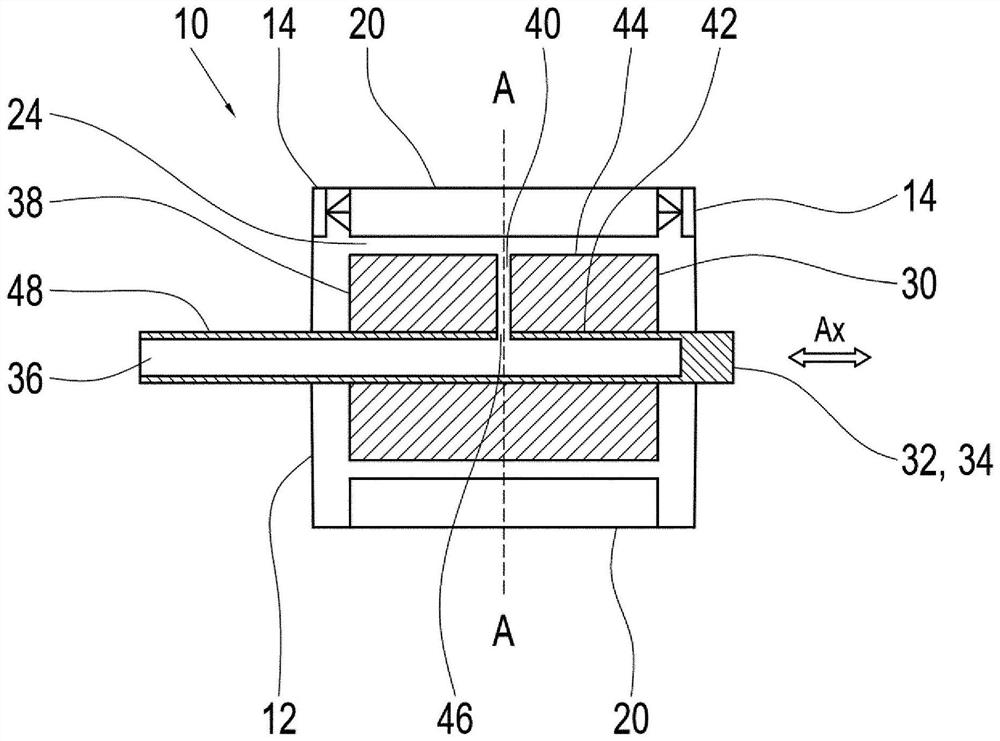
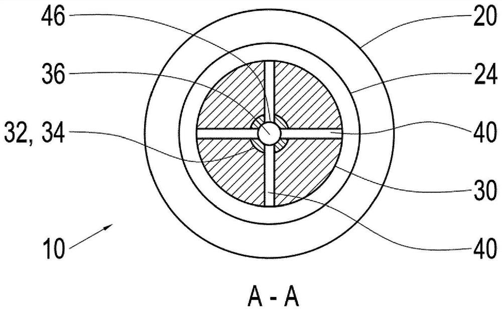
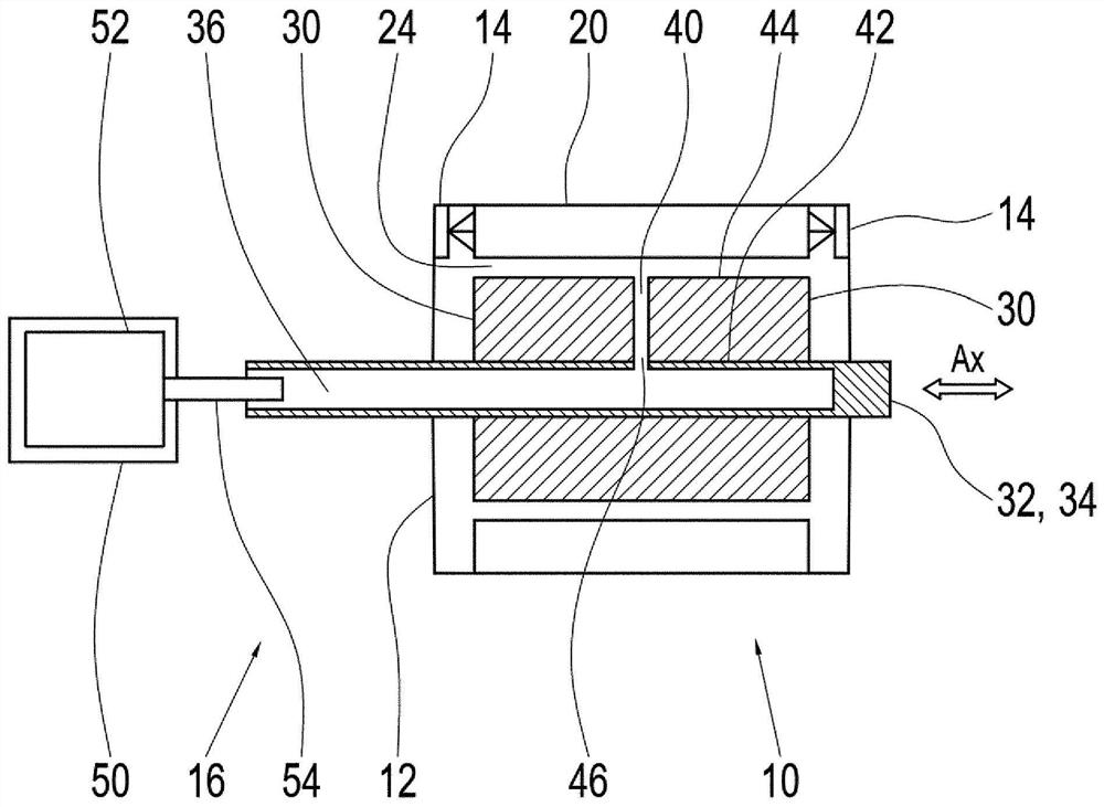
[0032] figure 1 An electric machine 10 according to the invention is shown, which has a housing 12 and a rotor 30 with a rotor shaft 32 in which a stator 20 is arranged in a stationary manner. The electric machine 10 of cylindrical design is arranged such that the rotor 30 rotates within the stator 20 .

[0033] The housing 12 also includes a cooling device 14 which sprays a coolant, preferably an oil-based coolant, onto the axial side of the stator 20 in order to cool the stator 20 . The winding heads sprayed by the cooling device 14 arranged at the axial ends are not shown in the schematic sectional view of the electric machine 10 .

[0034] The stator 20 and the rotor 30 are arranged such that an air gap 24 is formed therebetween. By spraying the stator 20 with a cooling liquid, such as oil, it is possible for the cooling liquid to penetrate into the air gap 24 .

[0035] The rotor shaft 32 is designed as a hollow shaft 34 and has an axial bore 36 which extends into the ...


PUM


Abstract

The invention relates to an electric machine having a housing, a stator arranged stationary in the housing, a rotor having a rotor shaft, an air gap formed between the rotor and the stator, and a cooling device for liquid-cooling the electric machine, the rotor shaft having an axial bore in the axial direction, the axial hole at least partially extends into the area of the rotor; the rotor has a radially extending air channel which extends from an inner side in contact with the rotor shaft to an outer side facing the air gap; and the rotor shaft has a bore aligned with the air passage such that air can flow from the rotor shaft into the air gap. The invention also relates to a system and a vehicle comprising such an electric machine, and a method for generating an air flow in an air gap between a stator and a rotor of an electric machine.

Description

technical field [0001] The invention relates to an electric machine having a housing, a stator arranged stationary in the housing, a rotor with a rotor shaft, and a liquid cooling device for the electric machine. A cooling device, and the invention relates to a method for generating an air flow in an air gap between a stator and a rotor of an electric machine. Background technique [0002] In principle, electric machines used in drive technology have a stator and a rotor. The stator generally comprises stator laminations and suitable coil windings, by means of which a magnetic field is generated in order to place the rotor in rotational motion. Electric machines are generally designed cylindrically, wherein an outer cylindrical stator surrounds an inner also cylindrical rotor. At the axial ends of the stator, the coil windings form so-called winding heads in which a large number of current-carrying conductors are guided in a relatively small volume. Due to the close arran...

Claims


Application Information

Patent Timeline
Patent Type & Authority Applications(China)
IPC IPC(8): H02K1/32H02K9/19H02K9/26
CPCH02K1/32H02K9/19H02K9/26H02K2201/03H02K2205/09H02K3/24H02K9/193H02K7/006H02K7/003
Inventor U·凯尔
Owner ZF FIEDRICHSHAFEN AG
Learn More